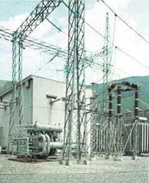
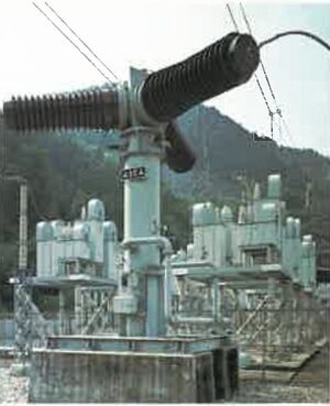
Milestone-Proposal:Sakuma Frequency Converter Station, 1965
To see comments, or add a comment to this discussion, click here.
Docket #:2025-18
This proposal has been submitted for review.
To the proposer’s knowledge, is this achievement subject to litigation? No
Is the achievement you are proposing more than 25 years old? Yes
Is the achievement you are proposing within IEEE’s designated fields as defined by IEEE Bylaw I-104.11, namely: Engineering, Computer Sciences and Information Technology, Physical Sciences, Biological and Medical Sciences, Mathematics, Technical Communications, Education, Management, and Law and Policy. Yes
Did the achievement provide a meaningful benefit for humanity? Yes
Was it of at least regional importance? Yes
Has an IEEE Organizational Unit agreed to pay for the milestone plaque(s)? Yes
Has the IEEE Section(s) in which the plaque(s) will be located agreed to arrange the dedication ceremony? Yes
Has the IEEE Section in which the milestone is located agreed to take responsibility for the plaque after it is dedicated? Yes
Has the owner of the site agreed to have it designated as an IEEE Milestone? Yes
Year or range of years in which the achievement occurred:
1965
Title of the proposed milestone:
Sakuma Frequency Converter Station, 1965
Plaque citation summarizing the achievement and its significance; if personal name(s) are included, such name(s) must follow the achievement itself in the citation wording: Text absolutely limited by plaque dimensions to 70 words; 60 is preferable for aesthetic reasons.
The Sakuma Frequency Converter Station, completed in 1965 by Electric Power Development Co., Ltd., enabled the first large-scale power exchange between Japan’s eastern 50 Hz and western 60 Hz grids via a 300 MW frequency converter based on mercury-arc rectifier. This achievement addressed a long-standing national frequency division, improving grid reliability, resilience, and laying the foundation for Japan’s future energy interconnection infrastructure.
200-250 word abstract describing the significance of the technical achievement being proposed, the person(s) involved, historical context, humanitarian and social impact, as well as any possible controversies the advocate might need to review.
The Sakuma Frequency Converter Station, developed and commissioned in 1965 by Electric Power Development Co., Ltd. (J-POWER Transmission Network Co., Ltd.), was Japan’s first large-scale facility to connect the country’s eastern 50 Hz power grid with the western 60 Hz grid. This pioneering project used a 300 MW frequency conversion system that used mercury-arc rectifier for bidirectional power exchange between the asynchronous grids. This system based on mercury-arc rectifier was the largest when the station became operation in 1965. The station’s supporting infrastructure included specially designed transformers, control and protection systems, and acoustic measures to minimize environmental impact. In 1993, the station was upgraded to a modern converter system using thyristors, enhancing efficiency and maintainability while preserving the original facility's legacy. As a critical link in Japan’s power system, the station enabled real-time power balancing between eastern and western Japan, greatly contributing to national grid stability and energy security. The successful implementation of this project marked a major milestone in Japanese power engineering. The Sakuma Frequency Converter Station is proposed as a significant IEEE Milestone for its historical and technical importance in overcoming Japan’s unique dual-frequency challenge.
IEEE technical societies and technical councils within whose fields of interest the Milestone proposal resides.
IEEE Power & Energy Society
IEEE Power Electronics Society
In what IEEE section(s) does it reside?
IEEE Nagoya Section
IEEE Organizational Unit(s) which have agreed to sponsor the Milestone:
IEEE Organizational Unit(s) paying for milestone plaque(s):
Unit: IEEE Nagoya Section
Senior Officer Name: Hideyuki Uehara
IEEE Organizational Unit(s) arranging the dedication ceremony:
Unit: IEEE Nagoya Section
Senior Officer Name: Hideyuki Uehara
IEEE section(s) monitoring the plaque(s):
IEEE Section: IEEE Nagoya Section
IEEE Section Chair name: Hideyuki Uehara
Milestone proposer(s):
Proposer name: Chiaki Ishikawa
Proposer email: Proposer's email masked to public
Proposer name: Kouji Takahashi
Proposer email: Proposer's email masked to public
Please note: your email address and contact information will be masked on the website for privacy reasons. Only IEEE History Center Staff will be able to view the email address.
Street address(es) and GPS coordinates in decimal form of the intended milestone plaque site(s):
Sakuma Frequency Converter Station, 219-1 Nakabe, Sakuma-cho, Tenryu-ku, Hamamatsu-shi, 431-3908, Japan.
GPS coordinate: 35.08222222,137.79916666
Describe briefly the intended site(s) of the milestone plaque(s). The intended site(s) must have a direct connection with the achievement (e.g. where developed, invented, tested, demonstrated, installed, or operated, etc.). A museum where a device or example of the technology is displayed, or the university where the inventor studied, are not, in themselves, sufficient connection for a milestone plaque.
Please give the details of the mounting, i.e. on the outside of the building, in the ground floor entrance hall, on a plinth on the grounds, etc. If visitors to the plaque site will need to go through security, or make an appointment, please give the contact information visitors will need. The plaque will be placed on Sakuma Frequency Converter Station, J-POWER Transmission Network Co., Ltd.
Are the original buildings extant?
Yes
Details of the plaque mounting:
The plaque will be displayed on the gate of office building, Sakuma Frequency Converter Station, J-POWER Transmission Network Co., Ltd.
How is the site protected/secured, and in what ways is it accessible to the public?
Visitors can come to office building of Sakuma Frequency Converter Station, J-POWER Transmission Network Co., Ltd. without security check.
Who is the present owner of the site(s)?
Sakuma Frequency Converter Station, J-POWER Transmission Network Co., Ltd.
What is the historical significance of the work (its technological, scientific, or social importance)? If personal names are included in citation, include detailed support at the end of this section preceded by "Justification for Inclusion of Name(s)". (see section 6 of Milestone Guidelines)
Social and Historical Significance
Bridging Japan's East-West Power Divide
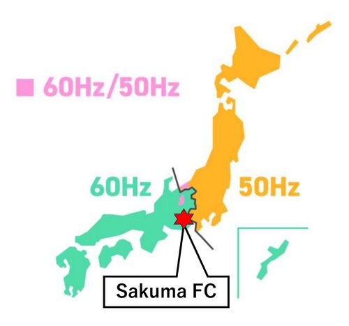
In 1895, Tokyo Electric Light Company adopted a "50 Hz" generator manufactured by AEG of Germany. Two years later, Osaka Electric Light Company introduced a "60 Hz" generator from General Electric in the United States. These early decisions led to the establishment of two separate frequency standards—50 Hz in eastern Japan and 60 Hz in the west—a division that persisted into the postwar era and complicated national power distribution, shown in Figure 1.
By the 1960s, the inability to transfer power freely between the two
regions had become a serious bottleneck for Japan's economic
development.
The Sakuma Frequency
Converter Station, completed in 1965, was Japan’s first large-scale
facility designed to directly address this problem [1-3, 7-9]. Instead
of attempting to synchronize the entire national grid, the station
introduced a large scale frequency conversion method
using mercury-arc rectifier to bridge the frequency divide.
Figure 1 Japan's electric power grid uniquely divided: 50 Hz in the east and 60 Hz in the west (Source: Reference [9])
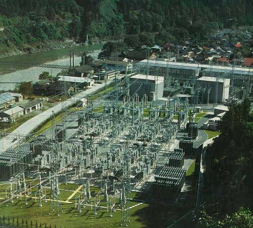
Photo 1 Sakuma Frequency Converter Station (Source: Reference [9])
Immediate Technical and Operational Benefits
Traditional methods of frequency conversion, such as dual-frequency
generation or isolated converter stations, were limited in capacity
and slow in response. Traditionally motor-generator systems had been used
for rapid bidirectional power exchange, allowing frequency decoupling and
real-time grid support.
But Sakuma Frequency Converter Station used a system based on
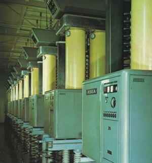
mercury-arc valve. The mercury-arc valve components were built by
Sweden's ASEA (Allmänna Svenska Elektriska Aktiebolaget).
The mercury-arc valve was used for high voltage direct current (HVDC) transmission in Gotland, Sweden.
The system used ASEA's mercury-arc valve.
A Japanese delegation saw the system in operation and suggested the
use of such a system in Japan, and eventually Sakuma Frequency
Converter Station was designed and built accordingly.
Operational simulations showed that regional blackouts—such as
frequency drops due to sudden generator outages in Tokyo—could be
substantially mitigated through immediate support from the western
grid via Sakuma.
This system eliminated the need for excess spinning reserves and
improved grid flexibility across the country.
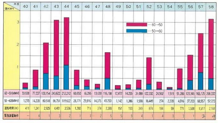
Figure 2 shows the operational status of the Sakuma Frequency
Converter Station from 1965 to 1983. The blue and red bar graphs
represent the amount of power transferred from 60 Hz to 50 Hz and from
50 Hz to 60 Hz, respectively. The numbers in the horizontal axis
section indicate the operating hours, while the orange numbers
represent the number of times the emergency power exchange was
activated.
Figure 2 Power Interchange 50Hz/60Hz on 1965-1983 (Source: Reference [9])
Pioneering High-Power Frequency Conversion
At the time of commissioning, Sakuma Frequency Converter Station was the largest frequency converter that used mercury-arc valve in the world. The station could transmit 300 MW power in both ways between 50 Hz and 60 Hz.
The facility was constructed with strong consideration for audible noise mitigation, electromagnetic compatibility, and long-term operational stability. Its success became a model for future grid-bridging systems.
Long-Term Impact on Japan's Energy Infrastructure
Sakuma laid the foundation for all subsequent East-West
interconnection projects in Japan. Though its original mercury-arc
valve technology was later replaced with thyristor valve converters
in 1993, the station remained central to grid balancing—especially
during emergencies such as the 2011 Great East Japan Earthquake, when
west-to-east energy transfer proved vital.
The core principle developed at Sakuma—connecting asynchronous grids while maintaining regional independence—continues to shape Japan’s modern power system, particularly as renewable energy and grid resilience gain importance.
A Technological and Strategic Milestone
Sakuma Frequency Converter Station was not only a technical breakthrough but also a strategic milestone in Japan’s postwar energy policy. It offered a robust and scalable solution to a century-old infrastructure split, enabling cross-regional cooperation and enhancing national energy security. The station’s implementation demonstrated Japan’s engineering leadership and has been referenced
in global case studies on asynchronous grid integration.
Technical Design and Innovation of Sakuma Frequency Converter Station
Overview of Purpose and Location
The Sakuma Frequency Converter Station was built to interconnect Japan’s 50 Hz and 60 Hz power grids, which are divided roughly along a line across central Honshū. Located about one kilometer from the Sakuma Hydroelectric Power Station in Shizuoka Prefecture, the converter station utilized existing 275 kV transmission lines, reducing the need for extensive new infrastructure [1-3, 7-9].
Construction began in April 1962 and was completed in November
1965. Its primary function was to enable stable, high-capacity
bidirectional power exchange between two asynchronous regions with
fundamentally incompatible grid frequencies.
Sakuma Frequency Converter Station
Overview
At the time of its commissioning, the Sakuma Frequency Converter Station employed
mercury-arc valve frequency conversion technology to transfer power
between eastern (50 Hz) and western (60 Hz) Japan.
This system decoupled the two grids and allowed independent frequency
control while facilitating controlled energy transfer. The system was
designed to transfer up to 300 MW of power with rapid direction
switching (in 0.2 second [10]) and excellent dynamic stability.
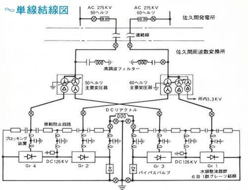
Its system layout is shown in Figure 3 as a single-line diagram.
Figure 3 single-line diagram (Source: Reference [9])
Figure 4 presents a simplified version to help explain how the system operates.
At the center of the facility is a DC reactor, with mercury arc rectifiers located on either side.
Surrounding these are block filters, surge suppression circuits, main transformers, and harmonic filter circuits. The entire system is symmetrical, with essential components arranged in order on both sides of the central DC reactor.
Figure 4 Simplified Block Diagram to explain how the system operates (Source: Reference [9])
Functions of the Main Components [4-6]
① Mercury Arc Rectifier (Core Facility):
Function: Converts alternating current (AC) into direct current (DC), and vice versa.
This is the most critical part for converting frequencies.
② DC Reactor:
Function: Smooths the direct current output from the mercury arc rectifier.
It reduces voltage ripple to deliver stable electricity.
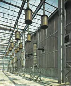
③ Block Filter:
Function: Eliminates radio-frequency noise generated by the mercury arc rectifier.
This prevents interference with nearby TVs and radios.
The filter is enclosed by an aluminum mesh, while a steel mesh is embedded in concrete flooring to block the noise.
④ Surge Suppression Circuit:
Function: Protects the system from electrical shocks that occur during conversion between AC and DC.
It absorbs electrical surges caused by large current transitions.
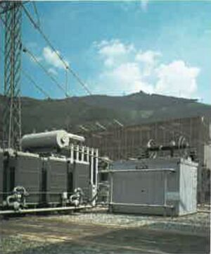
⑤ Main Transformer:
Function: Steps down the high voltage (275,000 volts) to a level suitable for rectifier operation, or steps it up in the opposite direction.
Since residential areas are nearby, it is installed indoors for noise reduction.
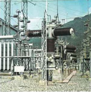
⑥ Harmonic Filter Circuit:
Function: Removes unwanted high-frequency components (harmonics) from the AC power that result from rectifier operation.
It restores the waveforms to the proper 50Hz or 60Hz standard.
In this way, the Sakuma Frequency Converter Station supports Japan’s
power grid by safely and reliably converting and transmitting
electricity between eastern Japan (50Hz) and western Japan (60Hz),
despite their differing frequencies.
What obstacles (technical, political, geographic) needed to be overcome?
Obstacles (Technical, Political, Geographic) Needed to Be Overcome
Technical Challenges
Designing High-Capacity Frequency Conversion
At the time, there was no precedent in Japan for transferring hundreds
of megawatts between asynchronous grids. Designing a
frequency conversion system with 300 MW capacity presented major
technical hurdles. The challenge included selecting appropriate rectifier
types, and ensuring mechanical and electrical stability.
This setup required advanced precision engineering and careful tuning
to prevent resonance, thermal distortion, or vibration under
changing load conditions.
System Control, Protection, and Reliability
Unlike synchronous grid connections, frequency converters introduce
unique control complexities. The Sakuma Frequency Converter Station had to manage:
- Smooth bidirectional power reversal,
- Voltage stability on both sides,
- Rapid response during frequency deviations or faults.
Redundant protection systems were deployed, including automatic shutdown triggers for voltage surges and loss of synchronization.
Vibration, Noise, and EMI Management
High voltage transformers in close proximity to residential areas
required advanced noise mitigation and vibration control. Engineers implemented
vibration isolation systems, underground foundations, and heavy
acoustic enclosures ([5]). Additionally, EMI shielding was used to prevent
interference with local radio and television signals—an uncommon but
critical requirement at that time ([3]).
Geographic and Environmental Constraints
Site Selection and Terrain Adaptation
The station was strategically located near the Sakuma Hydropower
Plant, making use of existing high-voltage infrastructure. However,
the mountainous terrain and seismic risk demanded careful site
preparation, including deep foundations and seismic isolation
techniques. Construction logistics were also challenging due to narrow
mountain access roads and limited space.
Environmental Compliance and Community Acceptance
Environmental impact was a major consideration from the outset. With
residential areas located nearby, strict noise and pollution limits
had to be met. The use of indoor transformers, soundproof buildings,
and quiet ventilation systems ensured compliance with
regulations. Local community engagement was also crucial in gaining
public acceptance for what was, at that time, a novel facility.
Grid Integration and Operational Complexity
Because Japan’s eastern and western grids operated independently, integrating a converter station that touched both systems introduced operational risks. Specialized protocols were developed for system startup, shut-down, fault management, and real-time dispatch coordination.
Political and Institutional Challenges
Cross-Regional Utility Cooperation
The project required unprecedented collaboration between eastern and western power companies, including Tokyo Electric Power Company, Chubu Electric Power Company and Kansai Electric Power Company. A special joint committee was formed under the Electric Power Council to align engineering standards, operating rules, and emergency protocols.
Policy and Regulatory Innovation
At that time, there were no existing standards for interconnection between asynchronous grids. New policies were developed to manage cost-sharing, tariff mechanisms, system responsibility, and power scheduling. Regulators worked closely with Electric Power Development Co., Ltd. and the utilities to formalize legal and operational frameworks.
Trial Operations and Grid Stability Testing
Before full operation, extensive testing was carried out over several
months beginning in mid-1965. This included frequency response
simulations, emergency drills, and step-load testing to validate
dynamic stability. Only after successful trials was the system placed
into commercial service in November 1965.
What features set this work apart from similar achievements?
What Features Set This Work Apart from Similar Achievements?
Overview of the Sakuma Frequency Converter Station
The Sakuma Frequency Converter Station, commissioned in 1965 and
located in Tenryu Ward, Hamamatsu City, Shizuoka Prefecture, was
Japan’s first large-scale facility designed to connect the country's
two separate power grids—eastern Japan (50 Hz) and western Japan
(60 Hz). It originally used mercury-arc valve frequency conversion
technology to achieve synchronous
decoupling between the two asynchronous grids. With a transfer
capacity of 300 MW, it enabled significant power exchange and laid the
foundation for national grid integration.
In 1993, the station was retrofitted with a modern converter system using thyristors, maintaining the original role
while enhancing efficiency and reliability. This evolutionary upgrade
demonstrates the enduring importance of the site in Japan’s power
system history.
Key Technical Features and National Importance
What set Sakuma Frequency Converter Station apart from others at the
time of its commissioning was not just the scale, but the fact that it
provided a practical and centralized solution to Japan’s
frequency-split problem, a direct consequence of early 20th-century
equipment imports from Germany and the United States.
Unlike long-distance HVDC systems used for bulk transmission, the
Sakuma Frequency converter Station was dedicated exclusively to intra-national frequency
conversion, ensuring energy security, grid flexibility, and mutual
support between regions during times of peak demand or emergency. It
was an operationally transformative project within a single country,
rather than an international link.
Comparison with European HVDC Systems
In Europe, most countries operate under a unified 50 Hz synchronous
grid coordinated by ENTSO-E (European Network of Transmission System
Operators for Electricity, website: https://www.entsoe.eu/ ).
While HVDC technology is used
extensively—for example, in cross-border submarine interconnectors
such as NorNed (Netherlands–Norway) and BritNed
(UK–Netherlands)—these systems primarily support energy trade and
geographic separation, not frequency conversion within a single
country.
Thus, although Europe adopted HVDC technology for similar reasons of
control, efficiency, and stability, it did not require a system like
Sakuma Frequency Converter Station to resolve fundamental frequency mismatches.
Comparison with North American Systems
North America, particularly the United States and Canada, operates
multiple large-scale asynchronous grids—such as the Eastern, Western,
and Texas (ERCOT, Electric Reliability Council of Texas, website:
https://www.ercot.com/) interconnections. These are linked via
back-to-back HVDC converter stations that serve as asynchronous ties,
similar in concept to the modern post-1993 Sakuma's solid state HVDC system.
Examples include the Miles City HVDC Tie and the Rapid City DC Tie,
which allow power transfer between asynchronous (same frequency) zones. (See
Western Area Power Administration web page: https://www.wapa.gov/transmission/functions/)
However,
even these systems typically serve significantly larger geographic
areas and were built later, reflecting evolving grid development in a
very different regulatory and geographical context.
A Unique Solution to a Unique Problem
Japan is the only industrialized nation with two commercial grid
frequencies within one country. This unique historical situation
required an equally unique solution: the Sakuma Frequency Converter
Station.
What made Sakuma Frequency converter Station distinct was its
mercury-arc valve (rectifier) to electronic technological evolution:
- Initially employing a system that used large-scale mercury-arc valves,
- Later transitioning to a thyristor valve system.
This dual-phase legacy illustrates both the adaptability and foresight of Japan’s power system engineers. The station remains one of the few sites worldwide that has functioned under both paradigms of frequency conversion.
Conclusion
The Sakuma Frequency Converter Station is a singular achievement in
the history of electrical engineering. Its original implementation of
high-power frequency conversion based on mercury-arc valve,
followed by a complete upgrade to solid state HVDC technology—all
within a consistent operational framework—sets it apart
globally.
Unlike other HVDC projects aimed at exporting electricity or linking
distant systems, Sakuma Frequency Converter Station addressed an infrastructural disconnection within a
single country, enabling national integration, improved energy
security, and enhanced grid flexibility. Its legacy continues to
inform modern approaches to asynchronous grid connection and frequency
coordination in Japan and beyond.
Why was the achievement successful and impactful?
Why Was the Achievement Successful and Impactful?
Bridging Japan’s Dual-Frequency Grid
The Sakuma Frequency Converter Station was a pioneering solution to a
uniquely Japanese infrastructure problem: the coexistence of two
commercial power frequencies—50 Hz in the east and 60 Hz in the
west. Prior to Sakuma Frequency Converter Station, interregional energy exchange was technically
limited and inefficient, relying on localized dual-frequency
generating units with low power and high operational cost.
By implementing a centralized frequency conversion system with a
300 MW capacity, Sakuma Frequency Converter Station allowed for meaningful and stable power
interchange between the regions for the first time. This greatly
enhanced grid flexibility, enabled emergency support during generation
shortages, and laid the operational groundwork for a more integrated
national power network.
Technical Innovation in Frequency Conversion
The original system employed a system that used mercury-arc valve and was the largest in Japan at that time, and the world's largest of its kind in 1965. The building of this converter station demanded advanced engineering in torsional stability, cooling, noise mitigation, and control.
Key technical innovations included:
- Heat endurance and mechanical endurance transformers that receive very high-frequency noise from the frequency conversion circuit,
- Acoustic insulation for community compatibility.
The Sakuma Frequency Converter Station’s design shared several operational objectives
with later HVDC applications, such as decoupling of asynchronous
networks and fast power direction reversal.
Enhancing Grid Stability and Operational Efficiency
The impact of the Sakuma facility was immediate and measurable. With
its ability to shift power between eastern and western grids in real
time, it:
- Reduced the need for regional reserve capacity, cutting operational costs,
- Improved frequency stability, decreasing frequency dips during outages,
- Enabled mutual emergency support, particularly in times of natural disaster, such as earthquakes or typhoons.
Simulations from the 1960s showed that a sudden loss of 340 MW in the
Tokyo region could result in a 0.8 Hz frequency drop—yet with the
Sakuma Frequency Converter Station in operation, this could be reduced to 0.4 Hz [1]. This
performance contributed to a more resilient and responsive national
power grid.
A Foundation for Future Development
The success of the Sakuma Frequency Converter Station not only solved
an urgent need in the 1960s, but also created a template for future
East–West grid interconnections in Japan. Subsequent converter
stations at Shin-Shinano (1977) and Higashi-Shimizu (2006) built on
the legacy of Sakuma Frequency Converter Station, taking advantage of
HVDC technology with solid-state thyristors.
In fact, Sakuma Frequency Converter Station itself was upgraded in
1993 from its original system that used mercury-arc valves to a
thyristor-based valve system, while maintaining the original station layout. This upgrade
reflected the advantages of the original design and the foresight of
its planners in anticipating future technological shifts.
Legacy of Engineering Excellence
Sakuma Frequency Converter Station demonstrated Japan’s capability to
engineer complex and durable power infrastructure under unique
constraints. It required innovation in mechanical and electrical
design, inter-company coordination, and long-term strategic
thinking.
The project remains an enduring symbol of:
- Cross-disciplinary engineering leadership,
- Technological adaptation over time,
- A nationally significant infrastructure solution that continues to serve the country six decades later.
Its continued operation—first using mercury-arc valves, now using thyristors
—embodies the evolution of electrical engineering and
Japan’s commitment to system resilience, grid flexibility, and
sustainable power delivery.
Supporting texts and citations to establish the dates, location, and importance of the achievement: Minimum of five (5), but as many as needed to support the milestone, such as patents, contemporary newspaper articles, journal articles, or chapters in scholarly books. 'Scholarly' is defined as peer-reviewed, with references, and published. You must supply the texts or excerpts themselves, not just the references. At least one of the references must be from a scholarly book or journal article. All supporting materials must be in English, or accompanied by an English translation.
Bibliography
Reference
[1] Susumu Kuwahara; “Sakuma Frequency Converter Station”, Vol. 85, No. 925, pp.1625–1634, The Journal of the Institute of Electrical Engineers of Japan, 1965.
[Translation to English: 1. Introduction]
1. Introduction
Japan’s electric power system is divided at the central region of Honshu Island, with the eastern side standardized at 50 Hz and the western side at 60 Hz. Within each of these two regions—excluding Hokkaido—all areas are interconnected via extra-high voltage transmission systems. By the end of 1965, the system capacity is expected to reach approximately 11,000 MW for the 50 Hz system and about 16,000 MW for the 60 Hz system.
The Sakuma Frequency Converter Station was constructed by the Electric Power Development Company (J-Power) with the goal of directly interconnecting these two frequency systems using direct current (DC) technology. The facility is outlined as follows:
Location: Sakuma Town, Iwata District, Shizuoka Prefecture (near Sakuma Power Station)
Output Capacity: 300 MW
AC Voltage: 275 kV
DC Voltage: ±125 kV
Construction Start: April 1962
Planned Operation Start: November 1965
Figure 1: Related System Diagram
The converter station is located approximately 1 km from the Sakuma Power Station and is connected to it via a 1.7 km-long 275 kV AC transmission line (with one line each for 50 Hz and 60 Hz on the same towers). From there, it links to the major power grids of Tokyo and Nagoya via the existing Sakuma East and West trunk lines. These system connections are shown in Figure 1.
The benefits of interconnecting the two frequency systems through the Sakuma Frequency Converter Station can be summarized as follows:
(1) Although switching between power plants designed for the two different frequencies (dual-cycle plants) is possible at a capacity of about 300 to 400 MW, such switching typically takes several minutes—up to around 15 minutes—and imposes operational constraints on the system. In contrast, DC interconnection avoids these drawbacks. Additionally, as thermal power development is rapidly progressing and the proportion of advanced large-scale thermal power within total generation continues to grow, relying solely on dual-cycle plant output for power interchange is becoming quantitatively insufficient.
(2) Calculations on the reduction of operating reserve have shown that, on a national scale, approximately 290 MW of reserve could be saved in 1964 and about 380 MW in 1968.
(3) In the event of a sudden loss of generation in one frequency system, emergency support from the other system via the frequency converter can significantly mitigate frequency drops in the affected system and help prevent cascading failures. For example, simulations for the 1964 system show that, in the event of a 340 MW outage at the Yokosuka Thermal Power Station in the 50 Hz system, frequency drop would be 0.33 Hz at peak load and 0.83 Hz under light load conditions (40% load). However, with DC interconnection, these drops would be limited to 0.14 Hz and 0.35 Hz, respectively.
[2] Shinzo Tamai and Hajime Yamamoto: “Power Conversion Technology Applications for Power Systems,” Transactions on IEE Japan, pp. 295–301, Vol. 121-D, No. 3, 2001.
[Translation to English: <2.1> pp. 1-4]
<2.1> Frequency Converter Stations (FC), Back-to-Back (BTB) Systems, and HVDC Transmission
In Japan's power grid, both 50 Hz and 60 Hz frequencies coexist. To address this, a 300 MW frequency converter (FC) was installed in Sakuma in 1965, followed by the introduction of the 600 MW Shin-Shinano and 300 MW Higashi-Shimizu stations.
[Translation to English: p.295, 2nd-column, pp. 12-15]
Internationally, the world’s first high-voltage direct current (HVDC) transmission using mercury-arc rectifiers began operation in 1954 in Gotland, Sweden. Today, over 50 HVDC systems are in operation worldwide, including the Itaipu system in Brazil, which has the world’s highest capacity at ±600 kV and 3150 MW. While most of these systems utilize thyristor-based equipment, self-commutated converters are beginning to be introduced for small-scale HVDC transmission and frequency conversion applications.
[3] Susumu KUWAHARA and Tatsuya TAKENOUCHI; “General Aspect of Sakuma Frequency Converter Station of The Electric Power Development Co.”, pp. 2-6, Mitsubishi Denki Giho, November 1965.
Media:Mitsubishi Denki Giho_1.pdf
[Abstract]
High voltage DC transmission technology was first developed in Sweden. In the year 1961 tie-lines of 160MW were laid over the Anglo-French Channel for commercial operation. The Electric Power Development Company, realizing that the DC transmission technique is applicable to frequency conversion equipment, set out to construct a Sakuma Frequency Converter Station for the purpose of tying via direct current the eastern power system at 50 cycles and the western at 60 cycles, the difference of which is a fatal drawback in this country. The station is slated to enter into commercial operation in the fall. The apparatus installed are unprecedented in this country and also the largest as AC to DC conversion equipment in the world. Description is made herein on DC machines as the major topics.
[4] Shozo TSUKAMOTO, Masao YANO, Kazuo SUZUKI, Teruo AIYAMA; “Pure Water-Cooling System in Sakuma Converter Station of the Electric Power Development Co.”, pp. 7-11, Mitsubishi Denki Giho, November 1965.
Media:Mitsubishi Denki Giho_2.pdf
[Abstract]
Temperature control is an important problem of a mercury rectifier
because its dynamic characteristics are influenced by the temperature
of the tank. Especially a high voltage high power converter requires
an extremely narrow limitation on the optimum temperature of the
cooling water, which is ±1°C in the case of Sakuma Converter
Station. Moreover, for a high voltage converter, insulation with
cooling water poses another problem. To reduce the length of the water
insulating pipe and to prevent the contamination of it, cooling water
of high purity is a vital requisite. This article reports on the pure
water-cooling system for a high voltage static frequency changer,
briefing the system meeting the demands.
[5] “Ryohei TAMURA, Kunikazu SAKATA”; “368 MVA, 353 MVA
Transformers for Sakuma Frequency Converter Station of the Electric Power Development Co.”, pp. 12-17, Mitsubishi Denki Giho, November 1965.
Media:Mitsubishi Denki Giho_3.pdf
[Abstract]
In 1958 3,000 kW 20 kV DC transmission equipment was manufactured by
Mitsubishi and supplied to connect Kyushu Takero Substation to Futago
Substation of the Mitsubishi Mining Co. Takashima mine. Only actual
results of commercial operation with regard to DC transmission were
made available there. But it is a matter of regret that the
engineering achievement on the DC transmission has been left neglected
since then. In the meantime, increase of recent power demand has come
to dictate the tying of the power systems of different frequency from
the viewpoint of the business operation in a broad range. This has
resulted in the installation of frequency converters by the Electric
Power Development Company at the site of Sakuma. Transformers to be
used for the purpose have been manufactured by Mitsubishi, being of
unparalleled capacity in the world.
[6] Ikuo YAMADA, Kimiharu OKAMOTO: “Analysis of Abnormal Phenomena in the Sakuma Frequency Converter of the Electric Power Development Co.”, pp. 18-24, Mitsubishi Denki Giho, November 1965.
Media:Mitsubishi Denki Giho_4.pdf
[Abstract]
Numerous abnormal phenomena are involved in high voltage high power
frequency converters. Analysis has been made on arc-back and
short-circuit current and DC excitation of transformer with the Sakuma
installation.
It is learnt that the current referred to enlarges with
the diminution of R/X and of control angle α. It also becomes larger
as arc-back θB approaches the spot right after the
commutation. By taking R/X, α and θB as input and the waveform and
magnitude of arc-back current as output, a computing program has been
developed. The DC excitation of transformer is considered due to the
slip of ripple current of different frequency systems tied, and to
irregularity of control angles of forward and reverse of the
converter. In the Sakuma installation, the latter predominating and
needs its diminution for the prevention of DC excitation.
[7] Takeshi MORI, Shigeo NISHINA and Hisashi NAGAMACHI: “AC Circuit Protection and Switchboards in Sakuma Frequency Converter Station of the Electric Power Development Co.”, pp. 25-36, Mitsubishi Denki Giho, November 1965.
Media:Mitsubishi Denki Giho_5.pdf
[Abstract]
Sakuma frequency converter station receives electric power from Sakuma
power station over a 275 kV transmission line and operates to convert
power at 50~60 cycles. On the extra high voltage side of the main
transformers for use in conversion are set up filters to absorb higher
harmonics for the protection of the systems. On the other hand, power
for the control of station service auxiliary machines is obtained by
stepping down the high voltage power to 3 kV through delta connection
of tertiary windings of the main transformer on the 60-cycle
system. The power is connected to auxiliary circuits and also tied to
Sakuma power station. Of the control apparatus installed their AC
switchboard equipment with AC protective devices as the major assembly
is built and delivered by Mitsubishi.
[8] Yoshiyuki Nakamura; “Special Feature, Energy and Energy Facilities: Overview and Structure of the Sakuma Power Station and the Sakuma Frequency Converter Station”. pp. 33-38, Construction Planning for Execution, April 2012.
[Translation to English: Chapter 6]
6. Construction of the Sakuma Frequency Converter Station
The Sakuma Frequency Converter Station is referred to as “Sakuma
FC,” with "FC" standing for "Frequency Converter." The Sakuma FC was
completed and began operation on October 10, 1965. With its
commissioning, Japan’s power grid—previously divided between 50 Hz
in eastern Japan and 60 Hz in western Japan—became
interconnected. The operation of Sakuma FC significantly accelerated
the development of wide-area power system operation.
The reason Japan's electrical frequencies are split—50 Hz in the east
and 60 Hz in the west—dates back to the late 19th century. In 1895 ,
Tokyo Electric Light Company imported generators from AEG in Germany
(50 Hz), while Osaka Electric Light Company imported generators from
General Electric in the United States in 1897, which operated at 60
Hz. Each company subsequently built thermal power plants using their
respective equipment.
The difference in frequencies brought about numerous inefficiencies,
such as the need for separate reserve power in each region, the
inability to transfer electricity between regions, and differences in
electrical equipment standards. There was an attempt to unify the
frequencies shortly after World War II, but due to the unexpectedly
rapid pace of post-war economic recovery, unification was not
achieved.
The idea of interconnecting the two frequency systems began in the
fall of 1958 with a study tour on wide-area power system
operation. During this visit, attention was drawn to a project between
the United Kingdom and France to link their power grids via
high-voltage direct current (HVDC) transmission, involving the
purchase of 160,000 kW of equipment from a Swedish company. This
inspired the proposal to use similar frequency conversion equipment in
Japan.
In April 1961, the Central Research Institute of Electric Power
Industry established the "Interconnection of Two Frequency Systems
Committee," chaired by Professor Setsuo Fukuda of the University of
Tokyo, to study the technical aspects of the project.
Land preparation for the site began in January 1963. The first
shipment of equipment from Sweden arrived at Nagoya Port in April
1964, and construction progressed rapidly. The station began operation
on October 10, 1965.
The main specifications of the Sakuma
Frequency Converter Station are as follows:
- Approved Output: 300,000 kW
- Converter Type: Mercury-arc rectifier
- Voltage × Current: 125 kV × 1,200 A
- Capacity per Pole × Number of Poles: 150,000 kW × 2 poles
- Number of Units per Group × Number of Groups: 6 units × 4 groups
- Start of Operation: October 10, 1965 (Showa 40)
- Note: On June 11, 1993, operation began using newly replaced thyristor valves.
[9] J-POWER Chubu Regional Office: "Sakuma Frequency Converter Station" – Visitor Information Brochure.
Media:Sakuna FC Visitor Brochure.pdf
[Translation: p. 7]
A Dream of Frequency Unification:
In the early days of Japan’s electric power industry, many power
companies operated across the country, each using generators imported
from countries like the United States and Germany. As a result, the
frequencies also differed—Western Japan developed with the American
standard of 60 Hz, while Eastern Japan adopted the European standard
of 50 Hz. This mix of frequencies grew over time alongside the
expansion of the industry.
As the power grid expanded, the inconvenience of having two different
frequencies became more apparent, and frequency unification was
frequently considered. Although some degree of unification between
Western and Eastern Japan was achieved, full national unification
proved nearly impossible due to the enormous costs involved. Thus,
Japan came to be divided into two regions: one operating at 50 Hz and
the other at 60 Hz.
The Sakuma Frequency Converter Station brought this long-standing
dream closer to reality. J-POWER (Electric Power Development Co.,
Ltd.) utilized high-voltage direct current (HVDC) transmission
technology, which had been developed in Sweden at the time, to
complete the world's first 300,000-kilowatt frequency converter
station. Here, alternating current (AC) from one system is converted
to direct current (DC) using mercury-arc rectifiers, and then
converted back to AC at the other frequency—effectively connecting
the 50 Hz and 60 Hz systems.
[Translation: p. 8]
Economic Benefits of the Frequency Converter Station
Reduction in reserve power requirements:
To ensure a stable electricity supply and prevent blackouts, a certain
level of reserve generation capacity must always be
available. Previously, this reserve had to be maintained separately
for both the 50 Hz and 60 Hz systems. With the completion of the
Sakuma Frequency Converter Station, the two systems became
interconnected, allowing for a significant reduction in the overall
reserve capacity needed. This has resulted in considerable savings in
the construction and operational costs of power plants.
Efficient operation across regions:
By taking advantage of differences in water levels during the rainy
season between Eastern and Western Japan, supply and demand variations
among power companies, and differences in peak electricity usage
times, the station enables more economical power exchange and
effective use of surplus hydropower.
Rapid emergency power support:
In the event of an accident in either system, the station can
instantly provide emergency power support, prevent the spread of the
outage and avoid large-scale blackouts.
[10]
HVDC fifty years on
ABB marked the 50th anniversary of the world’s first HVDC link with a gathering on the Swedish island of Gotland.
Available online at: https://www.modernpowersystems.com/analysis/hvdc-fifty-years-on/?cf-view
Remarks: This is a history of HDVC development that occurred at a
Swedish electrical engineering company ASEA, which later became part
of ABB (website: https://global.abb/ ) through the merger with Switzerland's Brown, Boveri and Cie.
[11] Special issue on Sakuma Frequency Converter Station, Mitsubishi Denki Giho, November 1965 vol. 39
(Original Japanese: 電源開発佐久間周波数変換所機器特集)
Available online at: https://www.giho.mitsubishielectric.co.jp/giho/pdf/1965/6511.pdf
References [3], [4], [5], [6], and [7] appeared in this special issue.
Mitsubishi Electric created the transformer and other electronics
components that were connected to ASEA's mercury-arc rectifier, and
cooling system, and thus the company issued the special issue of its
technical report.
Recognition
[R1] The Institute of Electrical Engineers of Japan (IEEJ): “Sakuma Frequency Converter Station”, IEEJ's Denki no Ishizue (the cornerstone of electricity), 2017.
Media:IEEJ Recognition_2017.pdf
[Remarks] “Denki no Ishizue” is a recognition system established by IEEJ to honor pioneering people, technologies, places, and events in Japan's electrical engineering history that have significantly contributed to society, industry, and innovation. Entries must be at least 25 years old and meet historical, social, or educational value criteria.
[Citation] The Sakuma Frequency Converter Station, the world's first frequency conversion facility for electric utility use, commenced operation in 1965. It enabled the interconnection between Eastern Japan (50 Hz) and Western Japan (60 Hz)—previously separated—through the application of AC/DC conversion technology. Since then, it has served as a cornerstone for wide-area grid operation and power interchange, playing a vital role during periods of electricity shortages in Japan’s era of rapid economic growth, and in times of supply-demand crises triggered by natural disasters such as the Great East Japan Earthquake, contributing significantly to the development of Japan's electric power industry.
Appendix
[A1] Electric Power Development Co., Ltd.: Sakuma Frequency Converter Station "Construction Records", October 1967.
Media:Construction Records.pdf
[Remarks] This booklet contains numerous photographs from the time of the original construction of the Sakuma Frequency Converter Station.
Supporting materials (supported formats: GIF, JPEG, PNG, PDF, DOC): All supporting materials must be in English, or if not in English, accompanied by an English translation. You must supply the texts or excerpts themselves, not just the references. For documents that are copyright-encumbered, or which you do not have rights to post, email the documents themselves to ieee-history@ieee.org. Please see the Milestone Program Guidelines for more information. Please email a jpeg or PDF a letter in English, or with English translation, from the site owner(s) giving permission to place IEEE milestone plaque on the property, and a letter (or forwarded email) from the appropriate Section Chair supporting the Milestone application to ieee-history@ieee.org with the subject line "Attention: Milestone Administrator." Note that there are multiple texts of the letter depending on whether an IEEE organizational unit other than the section will be paying for the plaque(s). Please recommend reviewers by emailing their names and email addresses to ieee-history@ieee.org. Please include the docket number and brief title of your proposal in the subject line of all emails.
