Milestone-Proposal:Vacuum Fluorescent Display, 1967
To see comments, or add a comment to this discussion, click here.
Docket #:2024-26
This proposal has been submitted for review.
To the proposer’s knowledge, is this achievement subject to litigation? No
Is the achievement you are proposing more than 25 years old? Yes
Is the achievement you are proposing within IEEE’s designated fields as defined by IEEE Bylaw I-104.11, namely: Engineering, Computer Sciences and Information Technology, Physical Sciences, Biological and Medical Sciences, Mathematics, Technical Communications, Education, Management, and Law and Policy. Yes
Did the achievement provide a meaningful benefit for humanity? Yes
Was it of at least regional importance? Yes
Has an IEEE Organizational Unit agreed to pay for the milestone plaque(s)? Yes
Has the IEEE Section(s) in which the plaque(s) will be located agreed to arrange the dedication ceremony? Yes
Has the IEEE Section in which the milestone is located agreed to take responsibility for the plaque after it is dedicated? Yes
Has the owner of the site agreed to have it designated as an IEEE Milestone? Yes
Year or range of years in which the achievement occurred:
1967
Title of the proposed milestone:
Vacuum Fluorescent Displays, 1967
Plaque citation summarizing the achievement and its significance; if personal name(s) are included, such name(s) must follow the achievement itself in the citation wording: Text absolutely limited by plaque dimensions to 70 words; 60 is preferable for aesthetic reasons.
Vacuum Fluorescent Displays (VFDs) were first commercialized in 1967 by Tadashi Nakamura, founder of Ise Electronics Corporation. Replacing large, expensive high-voltage Nixie tubes, VFDs revolutionized the calculator industry in 1972 by showing symbols and numbers in a flat panel format. Offering exceptional visibility and durability, these character displays were widely used in home appliances, automobiles, industrial equipment, and consumer electronics through the 1990s.
200-250 word abstract describing the significance of the technical achievement being proposed, the person(s) involved, historical context, humanitarian and social impact, as well as any possible controversies the advocate might need to review.
The Vacuum Fluorescent Display, commercialized by Dr. Tadashi Nakamura in 1967, revolutionized the calculator industry and had a profound impact on various sectors such as home appliances, automobiles, and industrial equipment. Dr. Nakamura, founder of Ise Electronics Corp., developed VFDs as a low-cost, low-voltage solution to replace Nixie tubes. The technological innovation of VFDs offered exceptional visibility and durability, making them popular in numerous applications.
The historical context includes the calculator boom of the 1960s and 1970s, where VFDs were critical in cutthroat competition in the Japanese calculator market, which some called “calculator wars”. By the early 1980s, VFDs were produced in vast quantities to meet the demands of various industries. Dr. Nakamura’s collaboration with academic institutions and other corporations, such as the Noritake Group, underscores “frontier spirits” and “cooperative spirit” in technological advancement.
Dr. Nakamura focused on the necessity of producing more efficient and reliable display technology at a lower cost and operating at a low voltage. However, there are several technical issues, and one of them is solved by viewing the display viewing in the opposite direction from the cathode side in comparison to the conventional CRT viewed from the anode side, like the “Egg of Columbus”. This inspiration led to the creation of the VFD, not only replacing the older Nixie tubes but also opening up new possibilities for various technological applications. The enduring legacy of VFDs lies in their continued production and relevance, even more than half a century after their development.
IEEE technical societies and technical councils within whose fields of interest the Milestone proposal resides.
IEEE Consumer Technology Society
In what IEEE section(s) does it reside?
IEEE Nagoya Section
IEEE Organizational Unit(s) which have agreed to sponsor the Milestone:
IEEE Organizational Unit(s) paying for milestone plaque(s):
Unit: IEEE Nagoya Section
Senior Officer Name: Jun Sato
IEEE Organizational Unit(s) arranging the dedication ceremony:
Unit: IEEE Nagoya Section
Senior Officer Name: Jun Sato
IEEE section(s) monitoring the plaque(s):
IEEE Section: IEEE Nagoya Section
IEEE Section Chair name: Jun Sato
Milestone proposer(s):
Proposer name: Kazunori Tatsuda
Proposer email: Proposer's email masked to public
Proposer name: Tomotaka Ezaki
Proposer email: Proposer's email masked to public
Proposer name: Takahiro Onishi
Proposer email: Proposer's email masked to public
Proposer name: Hiroyuki Matsumoto
Proposer email: Proposer's email masked to public
Please note: your email address and contact information will be masked on the website for privacy reasons. Only IEEE History Center Staff will be able to view the email address.
Street address(es) and GPS coordinates in decimal form of the intended milestone plaque site(s):
670-5 Uchimi, Taiki-cho, Watarai-gun, Mie 519-2736 JAPAN, GPS coordinates: N 34.410162, E 136.470089
Describe briefly the intended site(s) of the milestone plaque(s). The intended site(s) must have a direct connection with the achievement (e.g. where developed, invented, tested, demonstrated, installed, or operated, etc.). A museum where a device or example of the technology is displayed, or the university where the inventor studied, are not, in themselves, sufficient connection for a milestone plaque.
Please give the details of the mounting, i.e. on the outside of the building, in the ground floor entrance hall, on a plinth on the grounds, etc. If visitors to the plaque site will need to go through security, or make an appointment, please give the contact information visitors will need. Noritake Itron Corporation headquarters. Corporate building.
Are the original buildings extant?
No, Since the original building from when Ise Electronics Corp. was founded has already been demolished and no longer exists, the milestone plaque will be placed in the existing head office building. This head office building was constructed in 1969 for the mass production of VFDs and the adjacent building is still the only factory in Japan that manufactures VFDs.
Details of the plaque mounting:
In the ground floor entrance hall of main building.
How is the site protected/secured, and in what ways is it accessible to the public?
The entrance hall is monitored by a security system 24/7. Visitors can come to the entrance hall without security check.
Who is the present owner of the site(s)?
Kazuhiro Shinohara, President of Noritake Itron Corporation.
What is the historical significance of the work (its technological, scientific, or social importance)? If personal names are included in citation, include detailed support at the end of this section preceded by "Justification for Inclusion of Name(s)". (see section 6 of Milestone Guidelines)
Justification of Name in Citation
Dr. Tadashi Nakamura, the founder of Ise Electronics Corp., was born in Ise City in 1923 and studied electronic engineering at Nagoya Higher Technical School (now Nagoya Institute of Technology). Nakamura joined Kawanishi Machine Works (later Kobe Industry, now Denso Ten) in 1943, where he mastered vacuum tube technology while working on research into cathode ray tubes and phototubes [J3-1].
After World War II, Nakamura engaged in research and development of ultra-high frequency cathode ray tube. He invented the "Traveling-Wave Cathode-Ray Tube", and his paper on it was published in the IEE journal in October 1950 [O5], which became the basis of his doctoral dissertation [J3-2]. In 1962, Nakamura published a thesis entitled "Fundamental Problems in Display Tubes" [O15] and received a Ph.D. in Engineering from Osaka University [J1-8], [J3-2].
Nakamura continued his research and development as a professional engineer in electronic displays, inventing and successfully developing the single-electron gun color cathode ray tube [O16] and filing various utility model patent applications [O17], [O18].
However, the acquisition of Kobe Industry by Fujitsu [J1-1] threatened to close Nakamura's research opportunities, and the abrupt end of the transistorized portable color television project, Nakamura decided to go independent and start his own company to develop and sell his own technology [J1-15], [J3-3].
At the time when Dr. Nakamura decided to start his own company, the electronic industry in Japan was on the verge of a calculator boom [J3-4]. The first calculator in Japan was the CS-10A [O2], [O19], [J1-2], released in March 1964 by Hayakawa Electric (now Sharp). It is said to be the world's first all-transistor calculator, but its price was so high that it could buy a car [J1-3], it weighed 25 kg, and it used Nixie tubes for character display [J1-4], [J3-5]. The Nixie tubes operated at high voltages [J1-5] and had visibility issues having multiple electrodes displaced in depth as shown in Fig. 2 of US Patent 2962698 [O6]. Furthermore, the high patent fees to Burroughs were an obstacle to cost reduction for Japanese manufacturers [J1-6], [J3-6].
Therefore, Tadashi Sasaki, who was in charge of calculator development at Hayakawa Electric and Nakamura's former boss during his time at Kobe Industry and knew him well, had high hopes for Nakamura as a specialist of cathode ray tube, suggested and encouraged Nakamura to develop a new low-cost, low-voltage display tube for calculators [J3-7].
Nakamura had already experimented with zinc oxide phosphors, which he had discovered through his many years of research, to emit light at low voltages of just a few volts [J1-10], so he immediately investigated various technologies and came up with the basic concept of VFD that emitted light at low voltages.
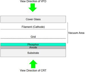
Nakamura's basic concept of VFD was based on combining a single-digit CRT with a triode vacuum tube. At the time, CRTs required hundreds of volts to excite the phosphor, but Nakamura knew that zinc oxide phosphor would luminesce at a much lower voltage. Furthermore, Nakamura also knew from his experience that viewing the luminescence directly from the side where the electrons hit the phosphor was brighter than viewing the luminescence through the phosphor layer as with CRT. This led to the "Columbus' egg" idea of a display tube that could be viewed directly through the cathode side, the opposite of a CRT [J1-12], [J2-2], refer to Figure 1-1 for the schematic of comparison between CRT and VFD.
Based on Nakamura's basic concept, Sasaki asked Masao Okubo, president of Japan Electronic Materials, to develop an extremely fine cathode [J1-9], [J1-13], and Nakamura asked Professor Katsumi Takagi of Shizuoka University and Takao Toriu of Dai Nippon Toryo to improve the brightness and extend its lifespan of the zinc oxide phosphor [J1-11], [J2-1].
In September 1966, Nakamura established Ise Electronics Corp. in Ise City to contribute to the development of the area where he was born and raised [J1-14].
Okubo of Japan Electronic Materials provided his R&D facility in Kyoto to Nakamura which was named "Kyoto Laboratory" [J1-9]. Nakamura and his company founding members of Ise Electronics stayed at the laboratory overnight and worked tirelessly to researching and prototyping VFD [J1-16]. As a result, Nakamura succeeded in developing prototypes of VFD [O1] in just two months [J3-8]. Having succeeded in developing VFDs, Nakamura began delivering prototype samples to Hayakawa Electric in March 1967 [J1-17], [J2-3].
The successful development of the VFD was reported in Electronics magazine, May 1967 issue [M1], [J1-19], which brought the VFD into the spotlight, and shortly after, it is also reported in Japanese newspapers [N1], [N2], [J3-11].
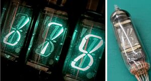
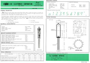
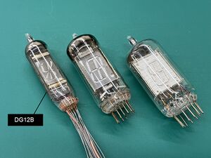
In September 1967, Hayakawa Electric officially decided to use a VFD, "DG12B" shown in Figures 1-2 and 1-3, for the world's first all-IC calculator, "CS-16A" [O2], [O3], [J1-21], and Ise Electronics began mass production of the VFD [J1-22]. This success of the commercialization of VFD was selected and awarded as one of the Nikkan Kogyo Shimbun's "top ten new products" in January 1968 [N3], [J1-20], [J3-11].
In October 1967, Mikiharu Tanji, one of the founding members and section manager of technology department who was responsible for designing the VFD and selecting the materials, applied for a U.S. patent for the VFD under Nakamura's direction, and it was registered in April 1970 [P1], [J3-10].
In recognition of these achievements, Nakamura was awarded the Society for Information Display (SID) Award twice, in 1979 and 1991 [A1], [A2].
The successful development of VFD at the time involved many technical experts and researchers from academia working together. The network of connections and vacuum tube technology knowledge cultivated at Kobe Industry played a significant role. The gathering of engineers from Kobe Industry, transcending organizational boundaries, led to the technological innovation of fluorescent display tubes. After the company's founding, Nakamura, the company president, stayed at the factory, and all employees worked tirelessly on research and development. As a result, they completed the prototype of the fluorescent display tube in just two months.
Pursuing the founding principle of "cultivating world-class technology through creativity and development" was also a notable feature. This involved gathering personnel during the venture stage and forming a network of joint research with universities and domestic and international partners. Nakamura’s collaboration with academic institutions and other corporations, such as the Noritake Group, underscores “Frontier spirits” and “cooperative spirit” in technological advancement.
Nakamura continued to dedicate his life to the development of the electronics industry as both a researcher and a technician, striving to sustain and grow his company.
Historical Significance
Background
In mid-1960s, the patent fees to Burroughs Corp. for Nixie tubes invented overseas were high, and light-emitting diodes (LEDs) were only commercialized as very expensive point-source indicators, with numerical display devices not yet completed.
Therefore, VFDs were adopted and technological advances were made to serve as calculator displays in the very competitive Japanese calculator market from the late 1960s to the 1970s. At that time, most displays in household appliances showing lines of characters or numbers in blue-green colors were VFDs rather than LCDs.
VFD Structure and Operation
Overview
In 1966, Tadashi Nakamura established the Ise Electronics Corp. (now Noritake Itron Corp.), and the Vacuum Fluorescent Display (VFD) was invented by him in 1967 [M1], [N1], [N2].
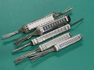
Initially, VFDs were round glass tubes displaying single digits. The first mass-produced VFD by Ise Electronics, the DG12B, was installed in Sharp's CS-16A, the world's first MOS-IC calculator [O2], [O3]. VFDs were also used in the "Casio Mini", known as the world's first personal calculator [O4], which displayed six digits by using six single digit tubes. Subsequently, multi-digit VFDs in a single vacuum tube were developed for cost reduction.
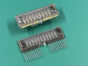
By 1972, flat panel VFDs capable of displaying multiple numbers and symbols were developed, expanding their applications [1].
Key characteristics of VFDs as devices are:
- Self-emissive with high brightness.
- Low operating voltage, directly drivable by LSI, with low power consumption.
- Easy multi-color display due to special phosphors.
- Flexible display patterns.
- Excellent heat and moisture resistance, suitable for various operating environments from high temperatures to extremely low temperatures.
VFD Structure
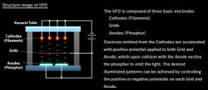
A VFD is a triode electron tube with a directly heated oxide cathode, a grid, and an anode that emits light, housed in a vacuum container with at least one transparent side shown in Figure 2.
The cathode, a tungsten core wire coated with ternary oxides of Ba, Sr, and Ca, is thin enough not to obstruct the display. The grid, made from a stainless steel thin plate processed into a mesh using photoetching, also does not obstruct the display. The anode, coated with phosphor on a conductor shaped into the desired display pattern, emits light when excited by electrons at low voltage.
As a vacuum tube, the main part of the enclosure is made of glass, similar to other vacuum tubes. By directing electrons from the cathode to the phosphor, the VFD is used as a display device for calculators and household electronic devices.
A similar technology is the cathode-ray tube (CRT), but it differs significantly in structure, such as using magnetic fields to deflect the beam of electrons emitted from an electron gun.
Observing the luminescence from the side where the electrons hit the phosphor makes it brighter than viewing the luminescence through the phosphor layer as with CRTs.
VFD Operating Principle
The cathode, made of tungsten wire coated with alkali metal oxides, emits thermal electrons when heated by an electric current. The grid, a metal mesh, accelerates and spreads electrons from the cathode to the anode by applying a positive voltage or blocks electrons from reaching the anode by applying a negative voltage to erase the display. The anode, coated with phosphor on a patterned conductor, emits light when electrons passed through the grid collide with and excite the phosphor when a positive voltage is applied.
VFD Applications
Overview
VFDs were widely used from the 1980s to the 1990s due to their excellent visibility and durability. They were widely used as display devices in home electronics such as TVs, audio equipment, video decks, and kitchen appliances.
VFDs were adopted in many consumer products due to their relatively low development and manufacturing costs, promoting widespread use.
They were also extensively used in industrial equipment, measuring instruments, and medical devices, contributing to increased work efficiency. Bright and clear displays provided accurate information to operators and technicians, improving work precision and safety.
High-density dot matrix VFDs capable of displaying Kanji characters and bitmap images were used in POS registers for displaying item names and change, VTR/VCRs, clocks, 7-segment displays, and custom-designed displays for each device, requiring easy-to-read characters and long display life.
Alphabet and Katakana Display
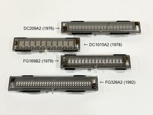
Initially developed as numeric display elements for calculators, the practical application of flat glass multi-digit tubes allowed the creation of arbitrary display patterns, leading to the development of 14-segment numeric and alphabetic display tubes and 5x7 dot character display tubes in 1976 as shown in Figure 3-1.
Due to the increased wiring density in the case of multi-line dot character displays, internal wiring using thick film became difficult. To address this, in 1978, Ise Electronics established a technology for wiring using photoetched aluminum thin films [2] as shown in Figure 3-2.
Automotive Meters
In the 1980s, this display device was particularly used by automakers for digital meters such as speedometers in onboard equipment, due to its bright, easy-to-read display and wide operating temperature range. The bright display made it suitable for electronic displays in automobiles. Until full-color LCDs replaced them, VFDs were used in the meter displays of the Toyota Prius series shown in Figure 4.
Game Machines
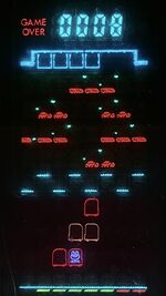
VFDs were also used in electronic game machines (early handheld game machines) from 1979 to the mid-1980s, due to its colorful, bright and clear visibility as shown in Figure 5. These game machines featured bright, clear displays, but since the size of the VFDs manufactured at that time was quite small, Fresnel lenses were used for magnification.
Early game machines achieved multi-color displays by passing the light emitted from the phosphor (typically green) through transparent color films. Subsequently, color phosphors for low-energy electron ray were developed, and game machines were equipped with sophisticated multi-color displays.
Graphic Display
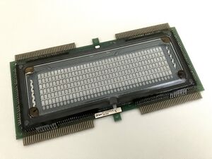
Initially, VFDs developed for displaying numbers, letters, and symbols evolved to meet the demands of the time, allowing the free display of graphics and Kanji with full-dot displays starting around 1977 shown in Figure 6. Initially, these were 20x20 dots with a 4mm pitch, but by 1981, high-density, large-capacity displays capable of displaying 128x128 dots with a 0.4mm pitch TV video image were developed [3], [6].
Early graphic VFDs were passively driven, requiring the number of leads to be at least equal to the number of horizontal plus vertical dots, making the assembly and installation of drive circuits challenging. In 1986, VFDs with built-in drivers were developed, reducing the number of terminals to about 20 for large-capacity displays, leading to wider adoption of graphic display tubes.
Ultra-Small Image Display
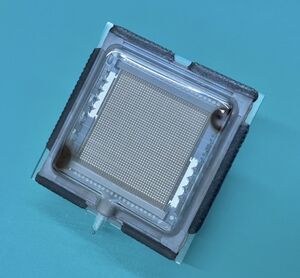
Achieving high-definition displays with dot sizes of about 0.1mm or less with VFDs was nearly impossible with the extension of the structures used for graphic display VFDs. Applying semiconductor microfabrication technology, an early active matrix fluorescent display tube was announced in 1980, formed by depositing phosphor on switching elements on a silicon chip [4], [P4].
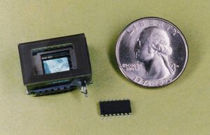
Subsequently, an ultra-small image display tube with 172x108 pixels within an 8x6mm screen was developed in 1983 for use as a viewfinder in video cameras shown in Figure 7 [5].
Although the ultra-small image display tube did not become widely popular due to cost and size issues, the technology of incorporating silicon chips within display tubes significantly contributed to the development of VFDs with built-in drivers.
Digital Signage
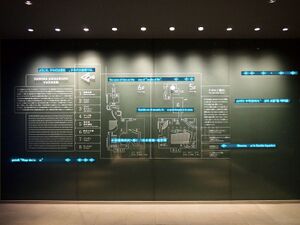
VFDs were also used in the development of digital signage and electronic billboards, utilizing their bright and attractive display characteristics. Notably, VFDs were highly valued and utilized in commercial facilities' spatial design, enhancing the aesthetics beyond merely conveying information. Examples include the use of VFDs for internal guide panels at the Sumida Aquarium shown in Figure 8.
Large Displays
In 1982, Mitsubishi Electric began developing a high-resolution, close-range Aurora Vision using VFDs of Ise Electronics. However, insufficient merging of light-guide emission elements resulted in image quality issues. The VFD display devices lacked sufficient brightness and longevity, with brightness rapidly decreasing under high brightness due to heat generation. In response, Mitsubishi Electric began developing a new light-emitting element, FMCRT [O1-2] collaborated with Ise Electronics using VFD manufacturing technology and CRT principles in 1985. By developing the FMCRT, the indoor Aurora Vision Mark II with a brightness of 1,300 cd/m2 was commercialized in June 1986 [7], [O2-2].
Sony Corporation exhibited the JumboTron [O7] at the 1985 International Science and Technology Exposition (popularly known as the Science Expo). This ultra-large display device, measuring 40m x 25m, utilized phosphor emission elements made by Futaba for its Trini-Lite [O1-3], light-emitting elements containing red, blue, and green emission parts.
Industrial Impact of VFDs
As mentioned earlier, the calculator industry, which used problematic Nixie tubes, paid attention to low-voltage fluorescent display tubes. When Sharp released the CS-16A calculator [O2] with the first installed VFD in December 1967 and after that, many calculator manufacturers proliferated, leading to price decrease and the start of a period known as the "Calculator Wars".
Consequently, Ise Electronics Corp. alone could not meet the demand, so the VFD patents were licensed to NEC and Futaba and production agreements were also signed with them to handle the rapidly increasing domestic and international demand [N3]. By the mid-1970s, the total annual production of VFDs reached 40 million units.
Subsequently, changes in the calculator industry and the emergence of LEDs and LCDs led VFDs to seek new markets and continue developing new products. As a result, VFDs found applications in clocks, automobiles, information devices, and other new markets, reaching an annual production volume of 90 million units in the early 1980s.
What obstacles (technical, political, geographic) needed to be overcome?
Overcoming Obstacles
VFDs were developed as low-cost, low-voltage numeric display devices for miniaturized and low-priced calculators. Technological innovations in VFDs were carried out in three stages [1], [2], [3], [4], [5], [6], with challenges and solutions at each stage summarized as follows:
Single-Digit Tube Development in 1967
The earliest VFDs were based on the idea of combining single-digit CRTs and triode vacuum tubes. At the time, CRTs required voltages of several hundred volts to excite the phosphor.
Dr. Nakamura knew that zinc oxide phosphor could luminesce at even lower voltages. Furthermore, he knew from experience that viewing the luminescence directly from the side where the electrons hit the phosphor was brighter than viewing the luminescence through the phosphor layer as with CRTs. This led to the "Columbus' egg" idea of a display tube that could be viewed directly through the cathode side, the opposite of a CRT [P1].
Practical implementation required extremely fine cathode wires that did not obstruct the view and highly efficient phosphors. With the cooperation of many technical experts and researchers from academia, electrode structures and phosphor formation methods were established and single-digit tubes were developed in 1967 shown in Figure 10. This development was announced in the Electronics magazine May 1967 issue [M1], followed by coverage in Japanese industry newspapers [N1], [N2], [N3].
The potential of VFDs was recognized, and production began in September of the same year.
The problems and solutions from the single-digit tube development:
- Lowering the cathode emission voltage: Adoption of zinc oxide phosphor instead of conventional CRT phosphors.
- Increasing brightness: Direct viewing of cathode-side luminescence instead of through the phosphor layer.
- Preventing the cathode from obstructing the view: Development of fine cathode wires by Japan Electronic Materials.
- Improving phosphor efficiency: Development cooperation with Dai Nippon Toryo and guidance from Professor Takagi at at Faculty of Engineering, Shizuoka University.
- Revising electrode structures: Switching from two-electrode to three-electrode tubes for higher brightness.
Multi-Digit Tube Development in 1971
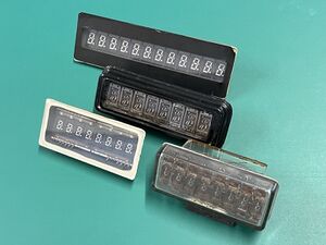
When using single-digit tubes in calculators, it was necessary to arrange several to twelve tubes, resulting in assembly work, brightness variations, and alignment inconsistencies. To address these issues, Ise Electronics Corp. developed and commercialized a multi-digit metal tube with a flat glass window in 1971 shown in Figure 11 [P2].
By encapsulating multiple digits in a single vacuum tube, the device became cheaper, and assembly work was significantly reduced shown in Figure 12.
NEC and Futaba also developed multi-digit tubes with multiple elements enclosed in a round glass tube. By 1972, each company shifted to 12mm round glass multi-digit tubes for handheld calculators.
The problems and solutions from the multi-digit tube development:
- Assembly work for using many single-digit tubes: Development of multi-digit tubes with flat glass and metal enclosures.
- Inconsistent display performance among single-digit tubes: Minimally noticeable variations by using a single vacuum tube.
Flat Panel Development in 1972
Traditional VFDs used ceramic substrates, which accounted for about 50% of material costs and were a major obstacle to cost reduction. Additionally, large ceramic substrates had issues with warping and dimensional accuracy.
To address these problems, the switch from ceramic to glass substrates was attempted [P3].
Despite challenges such as low electron emission from the cathode and low phosphor luminescence efficiency, these were overcome by 1972, and mass production began.
As a result, VFDs became flat panels with glass substrates as part of the enclosure, improving space factor shown in Figure 13.
The problems and solutions from the flat panel development:
- Cost reduction: Switching from ceramic to cheaper glass substrates.
- Warping and dimensional accuracy of large substrates: Ensuring flatness and dimensional accuracy with low-temperature-heated glass substrates.
- Low electron emission from the cathode: Solved by improving paste materials and optimizing heating conditions.
- Low phosphor luminescence efficiency: Solved by improving paste materials and optimizing heating conditions.
- Mass production challenges: Introducing new dedicated equipment due to different production processes from conventional products.
What features set this work apart from similar achievements?
Features Setting This Work Apart from Similar Achievements
VFD that can be driven at a lower voltage than Nixie Tube
Before the development of VFDs, calculators used Burroughs's Nixie tubes, which operated on the principle of gas discharge. Nixie tubes required driving voltages of around 200V, making IC driving difficult. Moreover, the numeric display method, which involved stacking metal electrodes, was time-consuming and each digit, such as "1", "2", "3", etc., were shown at different depth, resulting in poor visibility.
Additionally, high royalty was a significant issue. Consequently, calculator manufacturers in Japan eagerly sought the development of domestically-produced display tubes that were low-cost, low-voltage, and offered superior display characteristics. VFDs, developed to meet these demands, overcame Nixie tube shortcomings and were widely adopted in the calculator industry.
VFD that is cheaper than Light Emitting Diode
A light emitting diode (LEDs) is a type of diode that emits light when a voltage is applied in the forward direction. The red LEDs was invented by Nick Holonyak in 1962 [O8]. However, at the time of the development of the fluorescent display tube, commercial LEDs were extremely expensive and limited to indicator point light sources of infrared and red LEDs.
It wasn't until the late 1960s to early 1970s, when computers and watches started using LEDs displays, that LEDs became a significant business. Monsanto introduced the first commercial numeric display, the MAN-1A [O9]. HP and other companies also entered the numeric display market, leading to cost competition and a market share battle with VFDs. VFDs maintained their market by advancing multi-digit displays and reducing costs.
Self-illuminating VFD that is brighter than reflective Liquid Crystal Display
Liquid crystals are optical materials that possess both liquid and solid properties, and liquid crystal displays (LCDs) utilize the reorientation of liquid crystal molecules under voltage to modulate display images.
The existence of liquid crystals was discovered by Reinitzer in 1888 [O10]. In 1968, RCA in the United States developed a liquid crystal display device (cholesteric liquid crystal) [O11] that becomes opaque when a voltage is applied, scattering incident light; however, it did not reach commercialization.
In 1973, Sharp Corporation adopted LCDs technology for the display of its EL-805 calculator [O12], which used CMOS-LSI technology allowing battery operation.
Following this, LCDs became widely adopted for calculator displays, significantly reducing the use of fluorescent display tubes. However, LCDs of the 1960s to 1970s had several challenges:
- As "reflective" displays, they had poor contrast in low-light conditions.
- Their reliance on polarization limited the viewing angles.
- Low temperatures could cause dimming and slow response times.
In contrast, VFDs, being self-luminous, offered bright and clear displays, and their robustness in various temperature environments made them suitable for industrial and automotive applications.
Multi-color display devices
When LEDs were first developed, they were available only in single-color, either infrared or red. The high-brightness blue LEDs, using gallium nitride and mass-produced today for backlighting and illumination purposes, became practical in 1993. Consequently, LEDs at that time were not full-color.
LCDs were also monochrome displays during the 1960s and 1970s. The development of color LCDs technologies began with a paper on color filter methods for LCDs published by Professor Uchida of Tohoku University in 1981 [O13].
Japanese companies adopted this method and advanced the collaborative development between industry and academia, leading to practical applications and progress in color displays.
Initially, VFDs displayed only a single blue-green color. However, as their applications expanded, there was an increasing demand for multicolor displays. While there were many phosphors that could be excited by high-energy electron beams like in CRTs, phosphors other than green zinc oxide scarcely emitted light below 100V.
Research on phosphors that could emit light when excited by low-energy electron beams began around 1975 at Dai Nippon Toryo Co., Ltd. [O14], but their lifespan and luminous efficiency were insufficient. Improvements led to the practical application of two-color VFDs displaying green and orange by Futaba and Ise Electronics Corp. in 1978. This advancement preceded LEDs and LCDs in colorization, significantly enhancing display capabilities. Subsequently, phosphors for various colors were developed and commercialized, allowing for mass production of multicolor VFDs.
VFD developed in Japan and still evolving today
While the basic technologies for major displays such as LCDs, plasma displays, LEDs, OLEDs, and CRTs were mostly developed in Europe and the United States, the fundamental principles of VFDs were uniquely developed in Japan. At the time of development, considering the trends of other display devices, the product lifespan of a VFD was initially thought to be about ten years.
However, to meet customer demands, VFDs evolved from single-digit displays to multi-digit displays and flat panel formats capable of showing multiple numbers and symbols. This evolution was driven by unique ideas and technological innovations.
Moreover, leveraging their bright and easily visible characteristics and high reliability, new markets were continuously pioneered. As a result, even more than half a century after their development, VFDs are still being produced today.
Why was the achievement successful and impactful?
Compared to Nixie tubes, which were the most commonly used numeric display tubes at the time, VFDs had features such as a low operating voltage and low power consumption, which meant they could be driven directly by ICs, and they were self-illuminating, bright, easy to see, and had a long lifespan.
These features, and the fact that they did not infringe on the Burroughs patent, led to the success of VFDs, as they were able to meet the demand for electronic desktop calculators, which were experiencing rapid growth at the time.
VFDs were also easier to see than reflective liquid crystal display (LCDs), and had evolved to allow multi-digit displays, flat display tubes, alphabet and graphic displays, complex shape displays, and multi-color displays, as well as a wide operating temperature range and long lifespan, so they were used in a variety of applications that were difficult for reflective LCDs and ight emitting diode (LEDs) at the time.
Supporting texts and citations to establish the dates, location, and importance of the achievement: Minimum of five (5), but as many as needed to support the milestone, such as patents, contemporary newspaper articles, journal articles, or chapters in scholarly books. 'Scholarly' is defined as peer-reviewed, with references, and published. You must supply the texts or excerpts themselves, not just the references. At least one of the references must be from a scholarly book or journal article. All supporting materials must be in English, or accompanied by an English translation.
References
Paper
[4] S. Uemura, K. Kiyozumi; “Flat VFD TV display incorporating MOSFET switching array”, IEEE transactions on electron devices ED-28 No.6 P749-755 1981.
Retrieved 28 November 2024: https://ieeexplore.ieee.org/document/1481576
[Remarks] "Flat VFD TV display incorporating MOSFET switching array"
Abstract: A flat TV display panel was fabricated experimentally. It consists of an itegration of 241 × 246 picture elements to produce a picture size of 23 × 23 mm2. It operates upon a novel combination of fluorescent display elements and filament cathodes that emit electrons. It has a compact configuration, high light conversion efficiency with its low energy calhodoluminescent phosphor, and an integrated switching array. The operating principle of the new display panel and its experimental results, e.g., 10-fL luminescence at 30-V driving voltage and power consumption of 0.8 W (60 Hz, duty ratio of 1/300), etc. are depicted. In addition, the feasibility of incorporating memory function in the panel is discussed. Experimental results proved that memory function contributed to the reduction of power consumption, enhancement of brightness, improvement of resolution, and facilitation of color display.
Patent
[P1] PATENT 3508101 1970-04-21, Mikiharu Tanji, Character Indicating Electron Tube - VFD Basic Patent
[Remarks] Proposer's note: There is a typo in this patent document at around column 4-line 60 in page 3 of 4:
Typo: As described above, the numerals can be readily observed from the front of the tube, notwithstanding the presence of the cathode 25 or the grid 20 since they are both made of very fine wire.
Correct: As described above, the numerals can be readily observed from the front of the tube, notwithstanding the presence of the cathode 35 or the grid 20 since they are both made of very fine wire.
[P2] PATENT 3723789 1973-03-27, Mikiharu Tanji, Flat Composite Fluorescent Display Tube
[P4] PATENT 4081716 1978-03-28, Sashiro Uemura, Fluorescent Display Elements
Magazine
[M1] Electronics. McGraw-Hill., ISSN:00135070, May 29, 1967, P.212-213
Society for Information Display (SID) Awards
[A1] Certificate of SID Special Recognition Award in 1979
[Remarks] In May, 1979, The Society for Information Display has presented the Special Recognition Award to Tadashi Nakamura for innovative contributions to Vacuum Fluorescent Displays.
Screenshot SID website SID Special Recognition Awards
Retrieved 25 October 2024: https://www.sid.org/Awards/Individual-Honors-and-Awards/Special-Recognition
Retrieved 25 October 2024: https://www.sid.org/
[Remarks] The Society for Information Display (SID) is an industry organization for displays, generally electronic displays such as televisions and computer monitors. SID was founded in September 1962.
[A2] Medal and Certificate of SID Karl Ferdinand Braun Prize in 1991
[Remarks] In May, 1991, The Society for Information Display has awarded the Karl Ferdinand Braun Prize for outstanding contributions to Display Technology to Tadashi Nakamura and Kentaro Kiyozumi for the invention and development of the Vacuum Fluorescent Display.
Screenshot of SID website KARL FERDINAND BRAUN AWARD
Retrieved 25 October 2024: https://www.sid.org/Awards/Individual-Honors-and-Awards/KARL-FERDINAND-BRAUN-AWARD
[Remarks] The Karl Ferdinand Braun Prize is awarded for an outstanding technical achievement in, or contribution to, display technology. The award is made by the Board of Directors acting on the recommendation of the Honors and Awards Committee.
Newspaper
[N1] Dempa Shimbun Daily, July 21, 1967 Issue, P3
[Remarks] This newspaper article has been licensed to use by Dempa Publications Inc. on October 24, 2024.
[Remarks] "Ise Electronics to soon mass-produce new type of numeric display tube "Digitron"
Jointly developed with Hayakawa, driving voltage only 25V”
[N2] The Nikkan Kogyo Shimbun, July 17, 1967 Issue, P4
[Remarks] This newspaper article has been licensed to use by the Nikkan Kogyo Shimbun, Ltd. (Authorized No. N-24102401)
[Remarks] "Character display at about 25 volts"
"Ise Electronics develops "Digitron"
[N3] The Nikkan Kogyo Shimbun, January 25, 1968 Issue, P14
[Remarks] This newspaper article has been licensed to use by the Nikkan Kogyo Shimbun, Ltd. (Authorized No. N-24102801)
[Remarks] "The Struggles of Creating the Top Ten New Products No.3
Ise Electronics "Digitron" fluorescent character display electron tube
Others
Center of the History of Japanese Industrial Technology, Essential Historical Materials for Science and Technology
Retrieved 31 October 2024: https://sts.kahaku.go.jp/english/material/2023pdf/noe351.pdf
Registration in fiscal year 2023, Number 351, Single-digit Vacuum Fluorescent Display Tube (Prototype) - Bringing Japan's original display devices to the world -
Center of the History of Japanese Industrial Technology, Essential Historical Materials for Science and Technology
Retrieved 22 November 2024: https://sts.kahaku.go.jp/english/material/2023pdf/noe354.pdf
Registration in fiscal year 2023, Number 354, Light-Emitting Devices for Second-Gen Aurora Vision, (1) Matrix Light-Emitting Devices for Second-Gen Aurora Vision, (2) Display Unit for Second-Gen Outdoor High-Luminance Aurora Vision
Center of the History of Japanese Industrial Technology, Essential Historical Materials for Science and Technology
Retrieved 22 November 2024: https://sts.kahaku.go.jp/english/material/2024pdf/noe371.pdf
Registration in fiscal year 2024, Number 371, Trini-Lite for JumboTron (JTS-1)
Retrieved 30 October 2024: https://ethw.org/Milestones:Pioneering_Work_on_Electronic_Calculators,_1964-1973
Retrieved 22 November 2024: https://ethw.org/Milestones:Outdoor_large-scale_color_display_system,_1980
Retrieved 30 October 2024: http://www.dentaku-museum.com/calc/calc/1-sharp/1-sharpd/sharpd.html
[Remarks] "The CS-16A was an advanced calculator that not only used ICs, but was also the first in the world to use a fluorescent display tube. At the time, most calculators used Nixie tubes, patented by Burroughs in the United States. However, Nixie tubes consumed a lot of power at the time, and the patent fees were high, and Burroughs also required that calculators using Nixie tubes not be exported to the United States.
For this reason, Sharp had to make a calculator that did not use Nixie tubes at all costs. At the request of Sharp's Sasaki, Masao Okubo, who was the president of Japan Electronic Materials at the time, invented the fluorescent display tube (*). Tadashi Nakamura, who worked at Kobe Kogyo, left the company and established Ise Electronics, which succeeded in mass production. The world's first fluorescent tube was thus produced and was installed in the CS-16A. After the appearance of the CS-16A, the combination of MOS and fluorescent display tubes became the basis for calculators, and various calculators followed this approach. In that sense, the role played by the CS-16A was very significant."
[Remarks] (*) Proposer's comment: Proposer noticed that this sentence of the article may confuse the reviewers about the inventor of the VFD technology. Please note that it is objective facts that the actual and substantial inventor of the VFDs technology is Tadashi Nakamura by referring the above references of [A1], [A2], [M1], [N1], [N2], and [N3].
Retrieved 30 October 2024: http://www.dentaku-museum.com/calc/calc/2-casio/2-casiomini/casiomini.html
[Remarks] Mini. The first Mini was released in August 1972.
With a low price of 12,800 yen, this calculator was the forerunner of the "popular calculators" that were intended for personal use.
Looking at the inside, we can see that it used separate display tubes (single symbol display tubes).
Mini CM-601, Released in February 1973, six months after the release of the Mini.
Slightly longer and slimmer than the original Mini.
The display tube was changed to a round multi-digit tube (round tube).
Retrieved 20 November 2024: https://ieeexplore.ieee.org/abstract/document/1701109
[Remarks] Abstract: We have constructed cathode-ray tubes utilizing traveling waves, whose deflection sensitivity can be made independent of frequency by equalizing the phase velocity of the wave and the electron velocity. According to the theoretical analysis, the sensitivity of this tube is increased to 10-1 mm/v at 30 kMc without any difficulty. The results of the theoretical analysis are proved experimentally by the inversion spectrums. As examples of its application, measurements of amplitude modulation degree and observations of uhf voltage wave form are described in this paper.
Retrieved 26 November 2024: https://ieeexplore.ieee.org/document/1203072
[Remarks] Abstract: Light-emitting diodes are ubiquitous in today's high-tech world. But no matter what their application or color, their origin can be traced to the red LED created in 1962 by Nick Holonyak Jr., the winner of this year's IEEE Medal of Honor. The article describes Holonyak's career and the work which produced the first LED, and shows how his influence permeates the industry today.
Retrieved 26 November 2024: https://www.industrialalchemy.org/articleview.php?item=463
Retrieved 26 November 2024: http://www.industrialalchemy.org/storearticleview.php?item=101
[Remarks] Description: Monsanto MAN1A LED display, tested and working. The Monsanto MAN1, released in 1969, is considered by most collectors to be the first seven segment LED that was mass produced. The MAN1A is a colored epoxy version of the MAN1, which uses red plastic to hide the display's crude internal construction.
Retrieved 28 November 2024: https://chemistry-europe.onlinelibrary.wiley.com/doi/abs/10.1002/jlac.18460590117
Retrieved 28 November 2024: https://ieeexplore.ieee.org/document/1448443
[Remarks] Abstract: A new electrooptic effect in certain classes of nematic liquid crystals is presented. The effect has been termed "dynamic scattering" because scattering centers are produced in the transparent, anisotropic medium due to the disruptive effects of ions in transit. The ions can be produced by field assisted dissociation of neutral molecules and/or Schottky emission processes. The rise times of 1 to 5 ms and decay times of less than 30 ms, together with dc operating voltages in the 10 to 100 V range, make dynamic scattering seem attractive for such applications as alphanumeric indicators, and do not preclude its use in line-at-a-time matrix addressed, real-time displays. Reflective contrast ratios of better than 15 to 1 with efficiencies of 45 percent of the standard white have been demonstrated.
Retrieved 26 November 2024: https://global.sharp/corporate/info/his/only_one/item/t13.html
[Remarks] Also refer to [O2] Milestones: Pioneering Work on Electronic Calculators, 1964-1973
Patent No. Showa 52-23912, "Blue-emitting low-energy electron beam excited fluorescent display tube"
[Remarks] Japan Patent Office, Patent Publication, Showa 52-23912, Blue-emitting low-energy electron beam excited fluorescent display tube, application date June 30, 1975, publication date January 27, 1977
Claims: A low-energy electron beam excited fluorescent display tube having a structure in which an anode plate having a fluorescent film on one side and a cathode facing the fluorescent film are sealed in a container with a vacuum inside, characterized in that the fluorescent film is made of a blue-emitting composition made by mixing indium oxide and silver-activated zinc sulfide phosphor in a weight ratio of 1:9 to 9:1.
Patent No. Showa 52-23914, "Green-emitting low-energy electron beam excited fluorescent display tube"
[Remarks] Japan Patent Office, Patent Publication, Showa 52-23914, Green-emitting low-energy electron beam excited fluorescent display tube, Application date: July 4, 1975, Publication date: January 27, 1977
Claims: A low-energy electron beam excited fluorescent display tube having a structure in which an anode plate with a fluorescent film on one side and a cathode facing the fluorescent film are sealed in a vacuum container, the fluorescent film being made of a green-emitting composition made by mixing indium oxide and at least one of copper and aluminum activated zinc cadmium sulfide phosphor, europium activated strontium gallium sulfide phosphor, cerium activated yttrium aluminum gallium oxide phosphor, manganese activated zinc silicate phosphor, and terbium activated yttrium oxysulfide phosphor in a weight ratio of 1:9 to 9:1.
Retrieved 18 December 2024: https://ndlsearch.ndl.go.jp/books/R100000002-I000007816915
[Remarks] Japan Patent Office, Patent Publication, Showa 42-002785, 単電子銃型天然色受像管, Application date: March 27, 1964, Publication date: February 6, 1967
[Remarks] Japan Patent Office, Patent Publication, Showa 43-003714, 進行波陰極線管, Application date: June 16, 1964, Publication date: February 16, 1968
[Remarks] Japan Patent Office, Patent Publication, Showa 43-009617, 蛍光面内蔵型受像管, Application date: November 9, 1964, Publication date: April 26, 1968
Retrieved 19 December 2024: https://global.sharp/corporate/info/his/only_one/item/t08.html
Japanese Papers
[Remarks] In the early 1960s, there was talk of Fujitsu absorbing Kobe Industry. Fujitsu did not have the vacuum tube technology for telephone lines, and was at a disadvantage in the competition with NEC, which had the vacuum tube technology of the American company Western Electric. Therefore, Fujitsu intended to acquire the vacuum tube technology by absorbing Kobe Industry. However, by 1968, when the absorption by Fujitsu was completed, many engineers at Kobe Industry, who were unwilling to lose their free development environment, had left the company and moved to universities or private vacuum tube-related companies such as Futaba Corporation. One of them was Sasaki, who was the director of technology development at Kobe Industry and transferred to Hayakawa Electric in April 1964. At Hayakawa Electric, Sasaki worked on the development of a small, inexpensive calculator using transistors.
[Remarks] President Tokuji Hayakawa and Managing Director Akira Saeki of Hayakawa Electric had been paying attention to calculators, and had just released the world's first transistor calculator, the Compet CS-10A, in March 1964, just before Sasaki joined the company. Sasaki thought that if he could further advance the development of transistor technology and increase the circuit integration level with ICs (integrated circuits) and LSIs (large-scale integrated circuits), he could create a smaller, less expensive calculator.
[Remarks] Calculators at the time were large and expensive. For example, the price of the CS-10A was 535,000 Japanese yen.
[Remarks] One obstacle to realizing this foresight was the Nixie tubes used in calculator displays.
[Remarks] Nixie tubes emit a monochromatic orange light by applying a voltage to neon gas, and operate at a high voltage of 170 volts, so even if they wanted to use ICs as the driving circuit for calculators, there were no ICs that could operate at such a high voltage. There were also problems with poor visibility and a complicated assembly process.
[Remarks] In addition, Burrows, who held the patent, demanded large royalties, and the price of Nixie tubes, which was about 1,000 Japanese yen per tube, was not easily reduced. In order to reduce costs, they requested that royalties be paid based on a percentage of the price rather than the amount, but their request was not accepted. Nixie tubes were a major bottleneck in the pursuit of technological innovation in calculators.
[Remarks] So in the summer of 1965, Sasaki approached some of his acquaintances, engineers and researchers, to develop a new display device to replace Nixie tubes.
One of them was Nakamura Tadashi, who had been his subordinate at Kobe Industrial and was now head of the company's video tube technology department. After graduating from Nagoya Higher Technical School (now Nagoya Institute of Technology), Nakamura joined Kobe Industrial (then Kawanishi Machine Works) in 1943. During the war, he was mainly involved in research into night vision tubes and cathode ray tubes, and in February 1945, he joined the Army Tama Research Institute Radio Corps Training Center as a special radio soldier officer candidate, and was assigned to the 92nd Eastern Unit in charge of friendly force identification devices, which were scheduled to be deployed in September. After the war, Nakamura returned to Kobe Industry and developed cathode ray tubes as a specialist in electronic displays for radar and black-and-white televisions, based on the vacuum tube technology introduced by RCA. During this time, he received a doctorate in engineering from Osaka University for his research on electronic displays under the guidance of Professor Eiji Sugata, an authority on electron microscopes. Sasaki had high hopes for Nakamura's knowledge as a cathode ray tube engineer and approached him.
[Remarks] During this time, he received a doctorate in engineering from Osaka University for his research on electronic displays under the guidance of Professor Eiji Sugata, an authority on electron microscopes.
[Remarks] He also approached Masao Okubo, president of Japan Electronic Materials, which supplied cathode materials for cathode ray tubes to Kobe Industry, who offered the Kyoto Laboratory of Japan Electronic Materials as the base for development.
[Remarks] The first problem was that the phosphors in CRTs did not emit light at voltages below 100 volts. CRTs generally operate at voltages of 10,000 to 20,000 volts, and the phosphors would not emit light at the low voltages of several tens of volts required for calculators. This made it impossible to replace Nixie tubes. Nakamura recalled a basic study on zinc oxide (ZnO) phosphors he had read in the physics journal Physical Review. Zinc oxide is a material that emits light even at a few volts, and Nakamura himself had used it before. He had used it when he was asked by Professor Sugata, who had supervised him at Osaka University, to make an experimental tube for low-energy electron diffraction (LEED) at Kobe Technical High School. However, the light emitted by zinc oxide phosphors was dim. It was sufficient for analysis in a darkroom like LEED, but when used for displays, the brightness was far too low. Another problem was their short lifespan.
[Remarks] Is there any way to increase the brightness of zinc oxide phosphors and extend their lifespan? Professor Takagi Katsumi of Shizuoka University and Toriu Takao of Dai Nippon Toryo (later Kasei Optonix), who had been in a collaborative relationship with Kobe Industry on CRT phosphors since the days of Kobe Industry, were asked to look into this. Dai Nippon Toryo is a company with a history of receiving phosphor licenses from RCA after the war when Kobe Industry, Toshiba, and Hitachi introduced RCA's CRT technology, allowing all companies to use RCA's phosphor technology. About six months after the request, Takagi and Toriu succeeded in making significant improvements.
[Remarks] However, problems still remained. The second problem was that even with improvements to the zinc oxide phosphor, the brightness was still insufficient. Despite the efforts of Takagi and Toriu, it was clear that zinc oxide phosphors would not achieve the same brightness as CRTs. The key to overcoming this obstacle was Nakamura's idea that the image would be brighter if viewed from the opposite side to the CRT.
CRTs and Vacuum Fluorescent Displays have the same basic structure, where electrons are sent from the cathode to the anode, and the control electrode controls the collision with the phosphor. The difference is from which direction the display is viewed. CRTs are designed so that the light that passes through the phosphor screen where the electrons are colliding is viewed from the opposite side of the phosphor screen. Since the phosphor screen is not viewed directly, the brightness is reduced, but CRTs, which operate at high voltage and can obtain high brightness, can ensure sufficient brightness even when viewing the light that passes through. Nakamura's experience as a CRT engineer was put to good use in the innovative idea of making the CRT visible from the back. Nakamura thought that if the phosphor screen was viewed directly, the zinc oxide phosphor could provide sufficient brightness. In other words, the structure was designed so that the viewer could see through the cathode from the windshield side in Figure 2 (Proposer’s note: It is similar to the Figure 2 in this proposal). Nakamura described this idea as being like the "egg of Columbus," and said the following:
- “When I was working on CRTs, I could see the back side as well. I also made color CRTs, and the brightness is completely different whether you look at it from the front or the back. So if you look from the back, it's brighter from the side where the electrons are hitting.”
[Remarks] However, to realize this structure, it was necessary to form the cathode out of extremely fine wire so that it was not visible. Such cathodes had not been used in CRTs. This problem was solved by Okubo at Japan Electronic Materials, which had already developed extremely fine wire cathodes for a different purpose, provided the necessary technology.
[Remarks] In September 1966, Nakamura founded Ise Electronics in Ise, Mie Prefecture, and began commercializing Vacuum Fluorescent Displays. Nakamura was from Ise, and the capital of 20 million yen was provided through the intermediation of Sasaki, as well as support from Nakamura's relatives, local companies such as the Mie Regular Freight Truck Company, and Okubo of Japan Electronic Materials. At the time of the company's founding, Okubo was the president of Ise Electronics and Nakamura was the vice president, but shortly thereafter Okubo resigned and Nakamura became president. The company had 12 employees, including some from Kobe Industry.
[Remarks] Starting a company at a stage when it was still unclear whether Vacuum Fluorescent Displays could be commercialized entailed risks, but Nakamura said, "If we could make Vacuum Fluorescent Displays, that would be the best, but I wanted to do it myself anyway."
[Remarks] Although the company was founded, the Vacuum Fluorescent Displays were not yet at a level suitable for practical use. Further improvements were necessary. Nakamura and the other members of Ise Electronics worked desperately, staying overnight at the company to achieve a cost, performance, and quality that could be used for practical use.
[Remarks] Samples were delivered to Hayakawa Electric in March 1967.
[Remarks] It took several months for Hayakawa Electric to inspect the product, and it was not until September that they actually decided to adopt it. This was two years after Sasaki approached Nakamura and his team, and one year after Nakamura and his team founded Ise Electronics and began prototyping Vacuum Fluorescent Displays.
[Remarks] In order to expand business, the company also paid attention to PR. Making use of an old acquaintance from their days at Kobe Industry, they asked reporter Cohen from the American trade magazine Electronics to cover the factory in Ise city, and the article about Ise Electronics was published in the magazine in May 1967. The successful development of the Vacuum Fluorescent Display became a globally known event in the electronics industry.
[Remarks] In Japan, the development of the Vacuum Fluorescent Display was reported in the Nikkan Kogyo Shimbun in July of that year, and in January of the following year, it was selected as one of the newspaper's "Top Ten New Products" This was a valuable support and good publicity for the newly founded Ise Electronics.
[Remarks] In 1967, Hayakawa Electric released the CS-16A, the world's first all-IC calculator using a Vacuum Fluorescent Display. It was priced at 230,000 Japanese yen, less than half the price of the CS-10A, and had one-fifteenth the number of parts.
[Remarks] After this, calculators using Vacuum Fluorescent Displays began to increase, and Ise Electronics' production volume, which was around 3,000 units per month in 1967, rapidly increased to 30,000 units the following year, and by the 1970s it was producing one million units per month.
[J2] Genjiro Kosaka; “Extension of existing technology by a new company: The development process of Vacuum Fluorescent Display at Ise Electronics”, Organizational Science, Vol. 48, No. 4, The Academic Association for Organizational Science, 2015, P60-70 (in Japanese)
Retrieved 19 December 2024: https://www.jstage.jst.go.jp/article/soshikikagaku/48/4/48_60/_pdf/-char/ja
[Remarks] There were two main problems in the initial technological development process. The first problem was that at the low voltages used in calculators, electrons emitted from a vacuum tube and hit the phosphor did not emit light. Nakamura tried to solve this problem by applying the results of basic research on zinc oxide phosphor, which emits light even at low voltages. Nakamura had experience developing electronic display technology for radar and black-and-white televisions based on vacuum tube technology introduced to Kobe Industry by RCA in the United States, and so had knowledge of basic research in this field. In the development process to put this zinc oxide phosphor to practical use, support from Dai Nippon Toryo (later Kasei Optonix), with which Kobe Industry had a collaborative relationship in phosphor development during the time of Kobe Industry, was also instrumental.
[Remarks] The second problem was the lack of brightness of zinc oxide phosphor. Because calculator displays were driven by low voltages, the brightness of the display was insufficient compared to cathode ray tubes, which operated at high voltages. Nakamura's idea to solve this problem was to use a structure that was significantly different from that of cathode ray tubes, an idea he gained from his experience developing vacuum tubes and cathode ray tubes. Nakamura's idea established the basic structure of the VFD.
CRTs and VFDs are both products based on the principle of vacuum tubes, and have the same basic structure in which electrons are sent from the cathode to the anode, and the collisions with the phosphor on the anode side are controlled by a control electrode. The difference is from which direction the person looks at the emitting surface. As shown diagrammatically in Figure 2 (Proposer’s note: It is similar to the Figure 1-1 in this proposal), a CRT is designed so that the light that passes through the phosphor screen on which electrons are colliding is viewed from the side opposite the phosphor screen. Since the phosphor screen is not being viewed directly, the brightness is reduced, but CRTs can achieve high brightness through high voltage operation, so even viewing the transmitted light provides sufficient brightness. Nakamura's idea was that if the phosphor screen was viewed directly, then zinc oxide phosphor could provide sufficient brightness. In other words, the structure would be such that the cathode could be seen through the windshield side as shown in Figure 2. Nakamura described this idea as being like the "egg of Columbus," and said the following:
- "When I was working on CRTs, I could see the back side as well. I also made color CRTs, and the brightness is completely different when you look at it from the front and when you look at it from the back. So when you look at it from the back, it's brighter when you look at it from the side where the electrons hit it." (From lecture and interview with Tadashi Nakamura on May 10, 2007.)
In other words, Nakamura came up with the idea of increasing brightness by reversing the structure based on his previous development experience at Kobe Industry.
[Remarks] In 1966, one year after the start of development, Nakamura founded Ise Electronics, and the following year successfully delivered a sample VFD to Sharp. In the same year, 1967, Sharp released the CS-16A, the world's first all-IC calculator that used a VFD, and calculators equipped with VFDs subsequently became widespread.
[J3] Koji Hirao; “The history of growth of Noritake Itron Corporation - The trajectory of a research and development venture company -”, The monthly bulletin of Social Science, Vol. 495, 496, Institute for Social Science Senshu University, October 20, 2004, P79-94 (in Japanese)
Retrieved 19 December 2024: https://senshu-u.repo.nii.ac.jp/records/12085
[Remarks] The company's founder, Tadashi Nakamura, was born in Ise City in 1923. He studied electronics engineering at the Department of Electrical Engineering at Nagoya Technical School (now Nagoya Institute of Technology) and was employed by Kawanishi Machinery Works. At the time, the company was the only electron tube manufacturer in the Kansai region, and attracted talented engineers and researchers, including Tadashi Sasaki, who later became vice president of Sharp, and Nobel Prize winner Leo Esaki. There, he was involved in research and prototype development of phototubes, night vision tubes, and cathode ray tubes as military technology.
[Remarks] After the war, he returned to Kawanishi Machine Works (later Kobe Industry) and was in charge of developing cathode ray tubes in the technical department, where he succeeded in developing a cathode ray tube for ultra-high frequencies, the results of which were published in the American academic journal IEE and attracted international attention. Based on this research, he wrote a thesis on electronic displays and was awarded a doctorate in engineering from Osaka University. He also succeeded in developing a single electron gun color cathode ray tube for televisions. This rivaled the color television cathode ray tube technology of RCA in the United States and Telefunken in Germany, and was cutting-edge technology at the time.
[Remarks] While Nakamura was making progress in research and development of cathode ray tubes and display devices as a section manager of video tube section of the technology department, Kobe Industry was to be absorbed by Fujitsu. The vacuum tube and cathode ray tube divisions were scheduled to be closed as a result of the merger.
At this point, Nakamura had already been studying cutting-edge technology in electronics, vacuum engineering, ultra-high frequency engineering, and electronic materials for over 30 years since his student days, and was highly regarded as an engineer among experts and had achieved great results in research. He felt a sense of crisis that the merger of his workplace would close the door to research and development in that field.
In addition, Yaou Denki, which was working to commercialize an all-transistor portable color television that Nakamura had developed, stopped mass production. These two changes in circumstances motivated Nakamura to decide to start a company to "nurture his own technology and products and send them out to the world" based on technological development in a new field.
[Remarks] While Nakamura was making this decision, a calculator boom was about to begin in Japan's electronics industry.
[Remarks] The electronic calculator was an innovative product with high speed calculations, no noise, and the potential to become explosively popular, replacing conventional electric calculators. However, unlike modern calculators, it had drawbacks in that it was large, expensive, and required high voltage operation.
In particular, the character display used the "Nixie tube" developed by Burroughs in the United States. Since its development in 1950, this has dominated digital display technology.
[Remarks] Nixie tubes required high voltage (around 250 volts) to emit light based on the principle of neon gas discharge, and emitted a single color of orange light. The numbers were displayed by overlapping metal electrodes, which required assembly labor, and the numbers were difficult to read because they were not flat.
Furthermore, Burroughs held patents related to calculator manufacturing, so Japanese calculator manufacturers were required to pay a high patent royalty of 15%. This amounted to 45 cents compared to the selling price of one Nixie tube, which was 3 dollars, and was an obstacle to reducing the cost of calculators.
For this reason, calculator manufacturers were eager to develop a display tube using domestic technology that was low cost, had excellent display quality, and operated at a low voltage in order to popularize calculators.
[Remarks] Nakamura's boss at Kobe Industry, Sasaki Tadashi, had then moved to Hayakawa Electric where he was in charge of calculator production and development as the general manager of the industrial machinery, and he had high hopes for Nakamura's technology and encouraged Nakamura by suggesting that "Electronic calculators will grow greatly in the near future. There are many unsatisfied points in Burroughs' Nixie tubes. Calculators absolutely need a flat-screen display tube that operates on low voltage and uses little power. This is your area of expertise so you should definitely invent it.”
[Remarks] Under the direction of President Nakamura, who slept in the factory from the moment the company was founded, all employees literally worked overnight on research and development, completing prototypes of the Vacuum Fluorescent Display in just two months and reaching to sign a contract research for development of smaller Vacuum Fluorescent Display with Hayakawa Electric in November 1966.
The main reasons for this successful development in such a short period of time can be attributed to the high level of the group of engineers that had come together at the company and the clarity of the development goals, but it should also be noted that Nakamura also utilized his network of external resources.
[Remarks] They asked Japan Electronic Materials to help improve the cathode, the basic material of Vacuum Fluorescent Display, and Dai Nippon Toryo to help increase the brightness of zinc oxide phosphors.
[Remarks] After developing a prototype and struggling to reduce voltage, improve brightness, and improve the phosphor coating, the green light emission technology was completed in March 1967, and an international patent was applied for in April. Hayakawa Electric decided to officially adopt it for their calculators in September of the same year. This decision was a springboard for all employees to gain confidence and pride, making them realize that "Even if our company is small, if we can create an excellent product, it can be used all over the world."
[Remarks] As for marketing, is was a success to have Cohen, a long-time friend and a journalist of McGraw-Hill's electronics industry magazine Electronics, write an introductory article. This article instantly raised the company and its Vacuum Fluorescent Display internationally, and the positive reaction was imported back into Japan, with domestic media also running follow-up articles.
In 1968, they were awarded the Nikkan Kogyo Shimbun's Ten Great Inventions Award. As a result, they inundated with inquiries from major Japanese electronics manufacturers who were following in Hayakawa Electric's footsteps and starting to produce calculators.
[Remarks] The second is the founder's ambition, technical capabilities, and strong leadership. The company has always pursued its founding principle of "fostering world-class technology through creativity and development." This was achieved by gathering human resources at the Central Laboratory (Proposer’s note: the Kyoto Laboratory was closed in 1968 and new laboratory named “Central Laboratory” was opened in 1970 near HQs in Ise city.) at the venture company stage and forming a network of joint research with universities and domestic and international business partners. In particular, the company's collaboration with the Noritake Group, which has received capital investment, can be said to be a model case of collaboration between venture companies and large corporations (corporate venturing)
Supporting materials (supported formats: GIF, JPEG, PNG, PDF, DOC): All supporting materials must be in English, or if not in English, accompanied by an English translation. You must supply the texts or excerpts themselves, not just the references. For documents that are copyright-encumbered, or which you do not have rights to post, email the documents themselves to ieee-history@ieee.org. Please see the Milestone Program Guidelines for more information.
Please email a jpeg or PDF a letter in English, or with English translation, from the site owner(s) giving permission to place IEEE milestone plaque on the property, and a letter (or forwarded email) from the appropriate Section Chair supporting the Milestone application to ieee-history@ieee.org with the subject line "Attention: Milestone Administrator." Note that there are multiple texts of the letter depending on whether an IEEE organizational unit other than the section will be paying for the plaque(s).
Please recommend reviewers by emailing their names and email addresses to ieee-history@ieee.org. Please include the docket number and brief title of your proposal in the subject line of all emails.
