Milestone-Proposal:LORAN: Difference between revisions
From IEEE Milestones Wiki
(Article updated via HTTP request) |
(Article updated via HTTP request) |
||
| Line 1: | Line 1: | ||
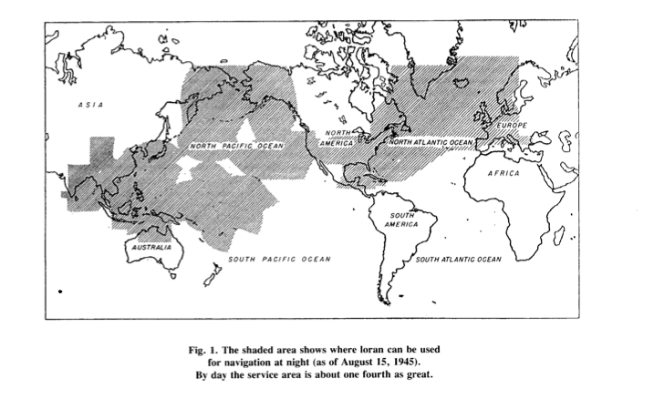
{{ProposalEdit|a1=LORAN|a2a=Cambridge MA|a2b=Boston Section|a3=1940 to 1946|a4=What is loran? Loran is a hyperbolic system of navigation by which difference in distance from two points on shore is determined by measurement of the time interval between reception of pulse- modulated synchronized signals from transmitters at the two points. The name loran is derived from long-range navigation. Both ground waves and sky waves can be used to provide coverage over an extensive area with few stations, depending on design frequencies. An important advantage of loran at the time of its development during WW2, was that a ship could use loran without breaking radio silence. Loran transmitting stations work in pairs. Synchronization is achieved by letting the signals of the master station, control those of the slave station. To help overcome the disadvantage of requiring two transmitting stations for a single family of hyperbolic lines of positions, loran forms a chain of stations, so that each station except the end ones operate with the station on either side to form an intersecting lattice of position lines. To find their way, loran navigators must have an radio receiver-indicator, a time piece, and a set of loran nautical charts or loran tables. Loran is also used for air-borne navigation. | {{ProposalEdit|a1=LORAN|a2a=Cambridge MA|a2b=Boston Section|a3=1940 to 1946|a4=What is loran? Loran is a hyperbolic system of navigation by which difference in distance from two points on shore is determined by measurement of the time interval between reception of pulse- modulated synchronized signals from transmitters at the two points. The name loran is derived from long-range navigation. Both ground waves and sky waves can be used to provide coverage over an extensive area with few stations, depending on design frequencies. An important advantage of loran at the time of its development during WW2, was that a ship could use loran without breaking radio silence. Loran transmitting stations work in pairs. Synchronization is achieved by letting the signals of the master station, control those of the slave station. To help overcome the disadvantage of requiring two transmitting stations for a single family of hyperbolic lines of positions, loran forms a chain of stations, so that each station except the end ones operate with the station on either side to form an intersecting lattice of position lines. To find their way, loran navigators must have an radio receiver-indicator, a time piece, and a set of loran nautical charts or loran tables. Loran is also used for air-borne navigation. | ||
Description | Description | ||
Loran consist of three components: 1. a chain of radio transmitters creating an electronic lattice or grid upon the surface of the earth. 2. a loran receiver-indicator, something like an electronic timer with a cathode ray tube and 3. loran nautical and aeronautical charts or tables published, for example, by the US Navy Hydrographic Office. | Loran consist of three components: 1. a chain of radio transmitters creating an electronic lattice or grid upon the surface of the earth. 2. a loran receiver-indicator, something like an electronic timer with a cathode ray tube and 3. loran nautical and aeronautical charts or tables published, for example, by the US Navy Hydrographic Office. | ||
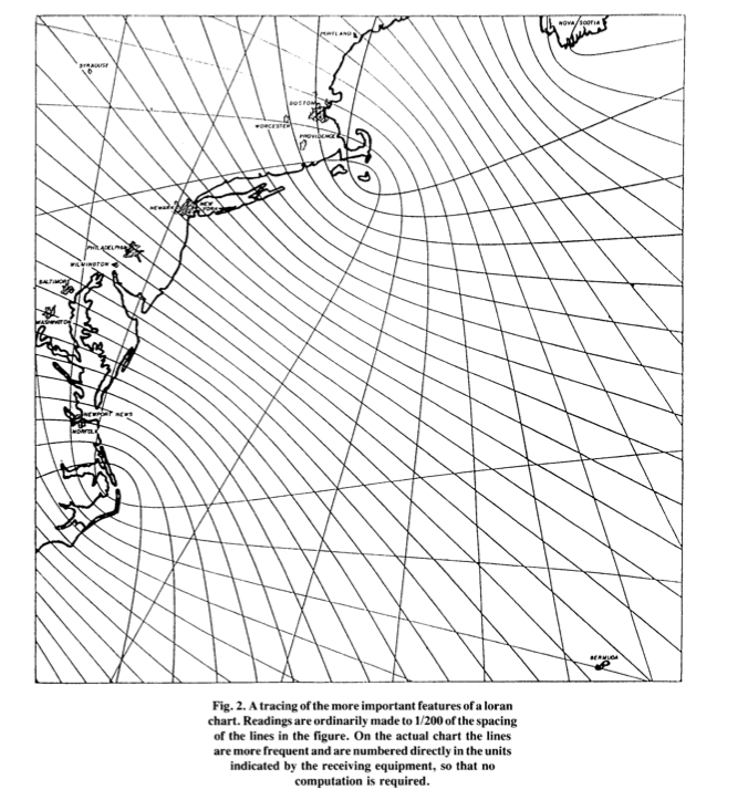
A simple explanation of how a navigator used loran in the 1940s to determine his position or fix follows next: first the line of position was established by measuring the relative time of arrival of two pulses which were known to have left two separate transmitters at times differing by a known interval. The time difference was noted in microseconds. With this information, charts and compasses, the navigator could plot a series of points on a chart plotting a line of position. No fix point yet. The navigator needs additional information to find the fix position. He may use a second pair of oran stations to determine a new line of position. Crossing of these two lines of position is the loran fix. For those wanting more details on the loran hyperbolic system of navigation, see Chapter X111 of Bowditch's American Practical Navigator. | A simple explanation of how a navigator used loran in the 1940s to determine his position or fix follows next: first the line of position was established by measuring the relative time of arrival of two pulses which were known to have left two separate transmitters at times differing by a known interval. The time difference was noted in microseconds. With this information, charts and compasses, the navigator could plot a series of points on a chart plotting a line of position. No fix point yet. The navigator needs additional information to find the fix position. He may use a second pair of oran stations to determine a new line of position. Crossing of these two lines of position is the loran fix. For those wanting more details on the loran hyperbolic system of navigation, see Chapter X111 of Bowditch's American Practical Navigator. | ||
shipboard navigators | shipboard navigators | ||
BRIEF DESCRIPTION | BRIEF DESCRIPTION | ||
| Line 65: | Line 62: | ||
Prepared in the Historical Section Public Information Division U.S. Coast Guard Headquarters Aug. 1, 1946 | Prepared in the Historical Section Public Information Division U.S. Coast Guard Headquarters Aug. 1, 1946 | ||
http://www.uscg.mil/History/STATIONS/loran_volume_2.pdf | http://www.uscg.mil/History/STATIONS/loran_volume_2.pdf | ||
REFERENCES | REFERENCES USED | ||
JA Pierce, "An Introduction to Loran", IEEE AES Magazine 1990 (attached) | JA Pierce, "An Introduction to Loran", IEEE AES Magazine 1990 (attached) | ||
Bowditch, American Practical Navigator.U.S. Navy Hydrographic Office, 1958 pp. 333 - 343 | Bowditch, American Practical Navigator.U.S. Navy Hydrographic Office, 1958 pp. 333 - 343 | ||
WEBSITES | WEBSITES | ||
THE COAST GUARD AT WAR. IV LORAN VOLUME II | THE COAST GUARD AT WAR. IV LORAN VOLUME II | ||
| Line 82: | Line 78: | ||
http://www.scribd.com/doc/35814242/MIT-Radiation-Lab-Series-V2-Radar-Aids-to-Navigation | http://www.scribd.com/doc/35814242/MIT-Radiation-Lab-Series-V2-Radar-Aids-to-Navigation | ||
TO PROBE FURTHER | TO PROBE FURTHER | ||
Willoughy, Malcom Francis; The Story of LORAN in the U.S. Coast Guard in World War II, Arno Pro, 1980 | |||
B.W. Sittelry, “ELEMENTS OFLORAN,” MIT Radiation Laboratoyr Re- port No. 499; March, 1944; also available as Navships 900, 027, Bureau of Ships, April 1944 | |||
Bureau of Ships, “LORAN HANDBOOK FOR SHIPBOARD OPERATORS,” Ships 278; July. 1944 | |||
Army Air Forces, “LORAN HANDBOOK FOR AIRCRAFT,” Air Forces Manual No. 37;published by training aids division, Officeof Assistant Chief of Air Staff, Training; September, 1944. | |||
Bureau of Ships, “LORAN TRANSMITTING STATION MANUAL,” Nav- ships 900,060A; March, 1945 | |||
J.A. Pierce, “THE FUTURE OF HYPERBOLIC NAVIGATION.” MIT Radiation Laboratory Report No. 625; August 1945 | |||
“THE LORAN SYSTEM,” Electronics, vol. 18, 00. 94-100, November, 1945;vol. 18, pp. 1IO- 116,December, 1945;and vol. 19,pp. 109-I 15,March, I946 | |||
Alexander A. McKenzie, “LORAN-THE LATEST IN NAVIGATIONAL AIDS,” QST, Part I , vol. 29. pp. 12-16. December, 1945; part 2. vol. 30, pp. 54-57. January, 1946; part 3, vol. 30, pp, 62-65, February, 1946 | |||
_|a5=The speed in which the LORAN system of navigation was initially designed, developed, constructed, placed into operations, manned 24/7 by radio technicians at isolated regions of the globe, is hard to explain. Even for a well-funded wartime crash program. Authors of this milestone proposal are not aware of anything similar to loran. | _|a5=The speed in which the LORAN system of navigation was initially designed, developed, constructed, placed into operations, manned 24/7 by radio technicians at isolated regions of the globe, is hard to explain. Even for a well-funded wartime crash program. Authors of this milestone proposal are not aware of anything similar to loran. | ||